-v ref

t06afre

Joined May 11, 2009
5,934
What kind of output voltage range do you need? What you also can look at is the LM723. That is also a good and simple starting point for power supply building. It would also help if you had any explanation for that circuit.
 

Shagas

Joined May 13, 2013
804
Hi
After 20+ years i desided to take up electronics again,and must admit being a bit rusty and outdated.
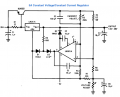
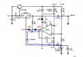
I making a new bench psu,the old suffered to much damage in the cellar.
See:http://www.circuitstoday.com/wp-con...nstant-current-constant-voltage-regualtor.png
I plan to use a 12v/5a smp for input voltage (no centerpoint)
but i need a -6v reference ,supplied from the 12v input if possible ?
Any solutions ?

Jan
You mean you want a +6 volt reference from the 12 volt for a dual supply?
 

t06afre

Joined May 11, 2009
5,934
I do not think that power supply will go down to zero volt. And I also think you will not be able to get 10 volt out with 12 volt input.
 

Thread Starter

speedless

Joined Jun 7, 2013
7
Hi
t06afre;you are right about the 10V,it will be around 9,5V
0V should be possibel with a negative reference voltage.

Jan

btw. I think your avertar needs a very long vacation
 
Last edited:

Jony130

Joined Feb 17, 2009
5,598
Hi

0V should be possibel with a negative reference voltage.
Jan
You have a error in diagram (R13). For correct diagram look at LM317 data sheet.


This circuit work as a normal LM317 voltage regulator. The output voltage equal to
Vout = 1.25* (1 + R8/R6)

So this circuit will never give you 0V at the output, unless you short the output to gnd. Vout_min = 1.25V. To be able to achieve 0V at the output.
You need to connect R8 pot to -1.25V instead of to ground. Or to -6V and add some additional resistance.

The current protection start to kick in when the load current is greater than

Isc = 1.25V• R2/(R3•R5) + Vbe/R1

Also 35v and 5A as seen in the datasheet are simply not possible, as they would kill the LM301A. And no single transistor will survive 35V*5A = 175W of power dissipation.
 

Attachments

Thread Starter

speedless

Joined Jun 7, 2013
7
Hi
Sorry,my mistake.
1.25V-9V output at 12V input.

"
You have a error in diagram (R13)"
? sorry,please explain (R13)?

"Also 35v and 5A as seen in the datasheet are simply not possible, as they would kill the LM301A. And no single transistor will survive 35V*5A = 175W of power dissipation."
The LM 301 is just for adjustment.
According to the data sheet of the MJ4502:200W.

While waiting for bits to arrive,I manage to repair my old 723 based PSU.(made 1982)
New potmeters and a lot of cleaning of oxidation did it.
So the 317 project is now for my Rasberry-pi box:for motors,servos...
The box will contain : raspi,gboard,auduino,servoctrl,dc-motor ctrl....

Jan
 

Jony130

Joined Feb 17, 2009
5,598
? sorry,please explain (R13)?
Circuit that you showed in the firs post that come from Circuits Today is an Indian site. And You should never trust any circuit that they put on the web.
What is the purpose of a R13 resistor from Circuits Today diagram ?
http://www.circuitstoday.com/wp-con...nstant-current-constant-voltage-regualtor.png

In the original diagram from LM317 datasheet. We can see R7 resistor.
And the job for this resistor is simply to limit LM301 current. When we set R8 pot to zero ohms or close to zero ohms. So R7 protect LM301 output against short circuits. And also protect R8 ( look at attached diagram).

But when we look at the circuit diagram from Circuits Today. We can easily see that they made catastrophic error during redrawing. R13 don't protect anything.

The LM 301 is just for adjustment.
According to the data sheet of the MJ4502:200W.
LM301 max Vcc = 36V. So for Vee = -6V give as only Vcc_max = 30V

Have you ever try to dissipate such a huge amount of power in a single BJT?
 

Attachments

Thread Starter

speedless

Joined Jun 7, 2013
7
Hi
Circuit that you showed in the firs post that come from Circuits Today is an Indian site. And You should never trust any circuit that they put on the web.
That wasnt nice.Watch out for INDIANS in the future!

Im going to try the circuit from national as shown in your post,wasnt aware it was an app. from national.Thanks!
The lm301 will be supplied from +-6V from ref.

Have you ever try to dissipate such a huge amount of power in a single BJT?
No and I dont intent to,but I will try and test it to its limits.

Jan
 
Top