Facebook
 Google
 GitHub
 Linkedin
Dear Sir/Madam,
I am new to this forum, not sure whether it is the right thread I posted here.
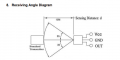
I want to use a home used remote control to turn on a motor to demonstrate the remote concept in class.
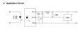
I have my own circuit design

I have several questions:
Best regards,
Kelvin.
I am new to this forum, not sure whether it is the right thread I posted here.
I want to use a home used remote control to turn on a motor to demonstrate the remote concept in class.
I have my own circuit design
I have several questions:
- When I use a multimeter to measure the voltage drop across the resistor and LED, it around -0.096V if no IR signal and 1.49V if IR signal. Do I use the wrong model of the transistor?
- Am I correct to place the LED at collector side of the transistor?
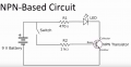
- Do I need to add a transistor between IR and base of the transistor?
- The output voltage is enough to light up a LED but not enough to a 3V motor if I replace a motor with the 150 ohms resistor and LED, should I increase the input power or replace with another model of the transistor?
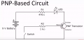
- Is there any better circuit design to do the same project?
Best regards,
Kelvin.
Attachments
-
 59.9 KB Views: 52