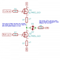
Sorry for the picture, it's a screengrab. I have two logic signals that will be going LOW when active. I thought I'd use a couple P-Channel enhancement -mode MOSFETs to do this. Will this work? Is there a better way?
The top one would work (if you reverse the drain and source terminals and use a logic-level P-MOSFET) but the bottom one won't because there's not enough gate-source voltage to turn it on (even for a logic-level type MOSFET, Vgs needs to be minus 3-5V).
The easiest solution is probably to use two N-MOSFETs or NPN transistors on the bottom (the first to invert the signal, and the second to turn on the LED).
When you want Q1 to be active and current flowing from the 6V supply through Q1 and the LED and to the 3V supply, you have only 1mA going through the LED.
When Q2 is active, you have 2mA going through the LED. Is that going to be bright enough?
Why not make Q2 an N-Channel, life will be much easier, assuming both Q1 and Q2 will be logic level MOSFETs
I read the specs, and I have the gate voltage going LOW (near GND) when I want to turn the lights on. I adjusted the series resistors, thanks for that.
I read the specs, and I have the gate voltage going LOW (near GND) when I want to turn the lights on. I adjusted the series resistors, thanks for that.
Never underestimate a guy that has already ordered his parts... According to the chart above, if I keep the resistor value to prop the source above the Gate ground by 1.5 V, I should have about .1 ohm, and that should conduct well enough? Then I'll need to lower the 220 ohm resistor to increase the diode current to about 5 mA?
View attachment 112778
Never underestimate a guy that has already ordered his parts... According to the chart above, if I keep the resistor value to prop the source above the Gate ground by 1.5 V, I should have about .1 ohm, and that should conduct well enough? Then I'll need to lower the 220 ohm resistor to increase the diode current to about 5 mA?
All kidding aside, I do not understand your comment. I thought that if I would be able to bring the gate voltage from -.45 to -1.2 Volts with respect to Pin 1 of Q2, it would start to conduct. Am I in error? I thought I knew how these devices work...
(and my snark...don't take it for face value...I appreciate your help.)
A MOSFET needs a bigger gate voltage drop than a pnp does. It will take 2 to 5 volts for a logic level mosfet to turn on all the way. You only need a few milliamps (maybe up to 20 mA) of current so you will not need all of the turn on (you can run in the linear range instead of the fully switched on range).
An standard MOSFET (not a logic level mosfet) typically is specified for 10V of gate voltage to turn on completely. You have less than 1 volt (assuming you remove resistor R4). If you keep R4, you will never get more than 2 mA through your diodes and your voltage drop from gate to ground will be small fractions of a single volt.
Your design might work enough to light the LED if you remove R4, AND put a 47 to 100 ohm resistor between Q2 and ground.
Thanks, I had put R4 in to limit the current in the LEDs before I put the other two in. I am going to get some little SMD to breadboard adapters to figure out the fine points of this, but basically, I have a board almost ready to go to OSH-Park and just needed to get some handholding.
Thanks, I had put R4 in to limit the current in the LEDs before I put the other two in. I am going to get some little SMD to breadboard adapters to figure out the fine points of this, but basically, I have a board almost ready to go to OSH-Park and just needed to get some handholding.
If you are sending a board in to have it made, then it is worth making it correctly. Make the few fine adjustments that are needed and get an NPN or N-channel mosfet for Q2. It would be a shame if Q2 does not turn on appropriately after spending the money on a board (or boards). Send me a private message with your address (click INBOX in upper right) - I'll send you a handful of the proper components.
Note that when you invert the top P-MOSFET and use an N-MOSFET or NPN for the bottom a GT suggested, you will need to invert the bottom signal for proper operation.
Below is a bridge circuit using two N-MOSFETs and two P-MOSFETS that will do what you want with only one supply voltage, and which gives symmetrical (equal) currents through the LEDs (or you could make them unequal by changing the relative values of R1 and R3).
Wow...I guess I've forgotten a lot since college. Yes, I see how this would work better and be balanced, to boot. I'm 59, but not too old to learn (forget, maybe). Thank you both kindly for your time and effort helping me. I do have the space for the six pin Alpha and Omega parts; is there a reason you picked these, or were they just easy to get to on the simulator? I haven't used PSpice for twenty years, guess I need to install the add-on for KiCad. What do you two use to simulate?
Wow...I guess I've forgotten a lot since college. Yes, I see how this would work better and be balanced, to boot. I'm 59, but not too old to learn (forget, maybe). Thank you both kindly for your time and effort helping me. I do have the space for the six pin Alpha and Omega parts; is there a reason you picked these, or were they just easy to get to on the simulator? I haven't used PSpice for twenty years, guess I need to install the add-on for KiCad. What do you two use to simulate?
............ I do have the space for the six pin Alpha and Omega parts; is there a reason you picked these, or were they just easy to get to on the simulator? I haven't used PSpice for twenty years, guess I need to install the add-on for KiCad. What do you two use to simulate?
I just picked those parts somewhat arbitrarily that were in my simulator library.
You can use just about any logic-level MOSFETs [Rds(on) specified at a Vgs of 5V or less].
I use the free LTspice simulator from Linear Technology.
Several on these forums use it. It's one of the better free simulators available.
Attached is my LTspice file.
 Facebook
 Google
 GitHub
 Linkedin