Using darlington transistor array to drive LEDs

Thread Starter

Fwacer

Joined Sep 1, 2017
3
Hi everyone,

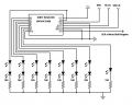
I'm uncertain on how to use my ULN2803A transistor array. I understand with regular npn transistors, you simply supply your larger current source to the collector pin, which goes to the emitter pin if toggled by a smaller current "switch" applied to the base pin.
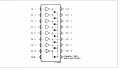
With this transistor array, there doesn't seem to be a Vcc pin, only a ground pin. Where is the larger current coming from? There is also a "common free wheeling diodes" pin, is this supposed to be tied to ground or Vcc?

Any clarification would be great! Thanks!


View attachment en.CD00000179 - transistor array.pdf
 

Attachments

AlbertHall

Joined Jun 4, 2014
12,345
You connect whatever you driving between your Vcc and the outputs of the chip. That's where the current comes from.
The common of the diodes is intended to be connected to Vcc also. The diodes will catch the back emf if you are driving an inductive load, e.g. a relay or motor.
 

WBahn

Joined Mar 31, 2012
29,979
What kind of LEDs are you driving that you need 500 mA of current? Certainly, these days there's a lot of LEDs out there that need more than this, but are you using them?

What I'm saying is that are you sure this chip is a good choice for what you are trying to do?
 

philba

Joined Aug 17, 2017
959
This diagram from the datasheet pretty much makes it clear. Out essentially sinks current. You use it pretty much like you'd use an NPN transistor as a driver.
2803A.png
 

Thread Starter

Fwacer

Joined Sep 1, 2017
3
Ah so this array is used to sink current, not source it? That is where I was misunderstanding.
Vcc to pin 10, got it.

What kind of LEDs are you driving that you need 500 mA of current? Certainly, these days there's a lot of LEDs out there that need more than this, but are you using them?

What I'm saying is that are you sure this chip is a good choice for what you are trying to do?
I've decided to simply drive the LEDs straight from the shift registers that I was planning to use to toggle the transistors, because I tested having two red LEDs in series with a 47R resistor (what I was planning to use for ~20mA draw per two LEDs) and using a 100R resistor, and I couldn't tell the difference in brightness. For two LEDs per segment (2.1V drop each) in my seven segment display, one shift register should be able to drive one display (~64mA draw with 8 segments, needed for part of the project) (70mA max per shift register).

Hopefully this doesn't mean a lower life on my LEDs (this is for a digital clock project).

After I decided this, I wanted to still learn how to use these arrays for future projects.

Thanks all for your help!
 

Attachments

philba

Joined Aug 17, 2017
959
If you are going to use a 595 to directly drive LEDs, then you should: put some 1K resistors in series with the 3 inputs and 50-100K pull downs on them as well. I used almost exactly that circuit and lost a number of 595s - the resistors fixed the problem. A bypass cap wouldn't hurt either.
 

Thread Starter

Fwacer

Joined Sep 1, 2017
3
If you are going to use a 595 to directly drive LEDs, then you should: put some 1K resistors in series with the 3 inputs and 50-100K pull downs on them as well. I used almost exactly that circuit and lost a number of 595s - the resistors fixed the problem. A bypass cap wouldn't hurt either.
What are the 1K resistors for? Could a higher current damage the inputs?
Do I need the pull downs if I am outputting from an arduino nano? I would imagine the nano's outputs wouldn't float all that much.
I am not familiar with a bypass cap (other than what a quick google search told me, removing AC noise). What value would I want and where would I place it? I've seen it in some schematics, but is it really necessary?
 

philba

Joined Aug 17, 2017
959
This is from about 8 years ago so my memory is a little fuzzy on it but I had a near identical circuit - 595s driving LEDs directly (only drove one LED per output). There were 2 to 4 595s in the chain driven from a PIC. I went through about 5 595s over the course of a week of testing. The circuit would work just fine for a while and then it was dead. I initially though that keeping the outputs from the PIC low (or high, not sure which) until needed would solve the problem but I kept on blowing 595s. I did a lot internet searching and found an old magazine article on interfacing 595s. The author discussed current inrush on the 3 input pins at start up and showed series resisters to limit the current and large pull-downs to keep the inputs well behaved. I tried that and never lost another 595. I went looking for the article but nothing came up. Lost my design notes in a system crash + backup fubar.
 
Top