Using an Ir sensor as clock signal

Thread Starter

ghghut

Joined Dec 30, 2023
13
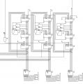
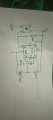
I'm making a score counter and i want to use the ir sensor as clock signal if there is an object in front of it. I connected a 74194 shift register to shift when theres an object in front of the IR sensor.

I made it in a breadboard but can't seem to shift or update the score display
 

Thread Starter

ghghut

Joined Dec 30, 2023
13
Hi ghg,
Please post your circuit diagram.
E
Here's the schematic. Im making a scoring system in my basketball arcade project and im using an adder to add to and have it's ouputs, inputs to the 74194 shifters.

The IR sensor output is the 0 on the left side. It is connected to the shifters clock input. The problem is it doesn't shift the display.
 

Attachments

Alec_t

Joined Sep 17, 2013
15,101
Have you checked that the IR sensor output actually gets to the counter input and that its rise and fall times meet the input timing requirements of the counter IC ?
 

Thread Starter

ghghut

Joined Dec 30, 2023
13
Have you checked that the IR sensor output actually gets to the counter input and that its rise and fall times meet the input timing requirements of the counter IC ?
Yes i am sure that the ir sensor is connected to the clock input of the 74194 shifter. For the timing requirements i think that's where the problem is, as i am relying on the detection of the ir sensor alone.

Im thinking attaching it to a delay timer should make it output enough time to the clock inputs to shift. Correct me if im wrong
 

Alec_t

Joined Sep 17, 2013
15,101
I can't see any requirement in the 74194 datasheet for maximum rise and fall times of the clock pulses, but delaying the pulses would not seem to offer any advantage. That IC does not have a Schmitt trigger clock input, so the rise and fall times probably need to be as small as possible. Someone else here may be able to say.
Btw, that IC is being discontinued by the manufacturer.
What is the spec of the IR sensor?
 

Thread Starter

ghghut

Joined Dec 30, 2023
13
I can't see any requirement in the 74194 datasheet for maximum rise and fall times of the clock pulses, but delaying the pulses would not seem to offer any advantage. That IC does not have a Schmitt trigger clock input, so the rise and fall times probably need to be as small as possible. Someone else here may be able to say.
Btw, that IC is being discontinued by the manufacturer.
What is the spec of the IR sensor?
I don't know the spec of the IR sensor i got since i bought it locally and it doesn't include any papers with it but I'll attach a picture below of the sensor.


The theory of making the delay timer as the clock input, was because i tried to input a clock pulse from a 555 timer and it did just fine.

This is the datasheet i found about the 74194 shifter
 

Attachments

Thread Starter

ghghut

Joined Dec 30, 2023
13
Can you test your circuit with a slow 1-Hz clock using a 555-timer IC?
Do you have an oscilloscope?

I don't have a oscilloscope. But i did connect it to a slower clock pulse earlier and it did just fine. That's why i came up with using a delay timer for the clock input and have the sensor output as always High and when it detects it should output Low for a second just like a button would with the schematic below.
 

Attachments

bertus

Joined Apr 5, 2008
22,883
Hello,

What IR sensor are you using?
Can you post a schematic on how you connected the IR sensor?
Does you sensor need a pull-up resistor?

Bertus
 

Irving

Joined Jan 30, 2016
4,996
7
The source of the IR sensor is 5v from the power rail.

The output doesn't seem to change when illuminated
No, I meant what are you using to illuminate the sensor? But I see its not just a sensor, its one of those obstacle avoidance boards. Here are some details:
1706100941682.png1706101006946.png

Let's make sure the board is working OK on its own, just vcc (+5v) and ground connections.. What are you powering the sensor from? ie what is your 5v source?

When you apply power the red LED D1 comes on? YES/NO

If NO, check vcc and ground connections. Or board is dead.

Is the green LED on? YES/NO

If NO, can you make it come on by turning the trimmer from one end to the other?

Set the trimmer mid-way, or some point where green LED is off. If you move your hand or other reflecting surface towards the sensor end of the board, does the green LED light up at some point? YES/NO

If NO, with a multimeter check the voltage across the pins of the clear emitter diode. It should be around 1.5 - 1.9 v. If its near 0 or near 5v then emitter diode is dead. If OK measure voltage across pins of the black receiver diode. This should approach 5v when the diode is completely covered ie no IR getting to it and progressively lower voltage the more iR gets to it - e the closer the obstacle. If that's not the case then the board is faulty.
 

Thread Starter

ghghut

Joined Dec 30, 2023
13
7
No, I meant what are you using to illuminate the sensor? But I see its not just a sensor, its one of those obstacle avoidance boards. Here are some details:
View attachment 313480View attachment 313481

Let's make sure the board is working OK on its own, just vcc (+5v) and ground connections.. What are you powering the sensor from? ie what is your 5v source?

When you apply power the red LED D1 comes on? YES/NO

If NO, check vcc and ground connections. Or board is dead.

Is the green LED on? YES/NO

If NO, can you make it come on by turning the trimmer from one end to the other?

Set the trimmer mid-way, or some point where green LED is off. If you move your hand or other reflecting surface towards the sensor end of the board, does the green LED light up at some point? YES/NO

If NO, with a multimeter check the voltage across the pins of the clear emitter diode. It should be around 1.5 - 1.9 v. If its near 0 or near 5v then emitter diode is dead. If OK measure voltage across pins of the black receiver diode. This should approach 5v when the diode is completely covered ie no IR getting to it and progressively lower voltage the more iR gets to it - e the closer the obstacle. If that's not the case then the board is faulty.

When power is applied, Yes the red LED turns on.

For the green LED it doesn't seem to turn on no matter how i adjust the trimmer.


I want to know is this okay a score detection? Or is an ultrasonic sensor be better??
 

Thread Starter

ghghut

Joined Dec 30, 2023
13
Hello,

What IR sensor are you using?
Can you post a schematic on how you connected the IR sensor?
Does you sensor need a pull-up resistor?

Bertus

It's those cheap obstacle detection one's i got, theres an image above in my replies.
 

MrChips

Joined Oct 2, 2009
34,628
1706108549755.png

With a DMM, measure the voltage across the pins on the IR Receiver.
The voltage should change as you move your hand far and close to the Emitter and Receiver.
 

sghioto

Joined Dec 31, 2017
8,633
It's those cheap obstacle detection one's i got, theres an image above in my replies.
I have one of those modules. The output is HIGH when no object is detected and goes LOW when detected using a LM393 comparator chip. Effective range is maybe 6 inches or more depending on the reflectivity of the object and how the module is mounted. I found turning the sensitivity up near max would activate the green LED with no object in front of it. Seems you may have a defective module.
 
Top