A Luxmeter (I had dinner across from Harold Luxenberg about 40 years ago, so I must have standing should have the same spectral response (a photopic response in particular) as the "standard" human eye. This is usually done with a precision color filter. Those can be expensive.
When I worked fora Taiwanese (monochrome at the time) CRT monitor manufacturer they used a silicon solar cell and a moving coil movement with a sensitive adjustment. They could then calibrate it by measuring a CRT display can comparing the reading with what we could call a "real" photometer. In that case, the amount of light being emitted was photonically consistent. In the case of a Luxmeter this does not always work out because varying spectral content of the light source.
There are some surface mount photometric sensors available from Taos Opto Electronics and possibly others, that can do a pretty good job of measuring light with a photopic response. That is the first place I would look for a sensor if designing a low cost Luxmeter. There may be other manufacturers of photopic photo sensors, but since I have been out of the business for decades I have not kept track, so take a look around for photopic sensors.
By the way, I once read that CdS cells were used in film cameras because they could be Made to have a photopic response good enough for an auto-iris circuit to produce reasonable results. A phototransistor is heavily weighted toward the longer wavelengths and even infrared.
Transistors change CE resistance (not all resistances are ohmic), you can model them as current controlled devices for operating parameters. View attachment 339637 View attachment 339640
It's not easy putting those tiny guys and girls in there.
The circuit seems pretty simple to breadboard for testing and tweaking.
I have done this in the past- it worked really well, with a fairly large dynamic range.
Super low parts count using a PHOTO DIODE in Photoconductive mode.
First the IO pin is set to OUTPUT and set HIGH level (cap charges to Vcc)
IO pin is set to INPUT mode, and the timer is started.
Stop the timer when the input reads LOW (interrupts help here)
The photocurrent discharges the cap at a rate proportional to the light level.
Read the elapsed time.
I managed about 12 bits of dynamic range with this scheme.
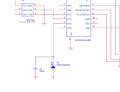
This is the "final" circuit I have settled on. Earlier versions were using a much lower value for R7 and so the signal was not having the proper range (always 0 and sometimes 0-3) Will have a PCB in hand in a month from China to actually test range.
The software works great:
I have a rolling queue of 10 values in a row (every 5 seconds) and get an average for the last 10. I also keep 2 values (min / max) of all values. So independent of the circuits and components, I can have an idea of the environment and this gives me a percentage between min-max. The algorithm worked with an LDR. Will see how it adapts to this setup. I already have 3 devices on the I2C line, so adding one more read was not difficult.
This method works well. We did something similar on a production line at WYSE in Taiwan. The only real issue was that if the display color changes, the calibration is void.
An improvement would be to add an appropriate photopic filter ahead of your photosenor.
 Facebook
 Google
 GitHub
 Linkedin
") should have the same spectral response (a photopic response in particular) as the "standard" human eye. This is usually done with a precision color filter. Those can be expensive.
should have the same spectral response (a photopic response in particular) as the "standard" human eye. This is usually done with a precision color filter. Those can be expensive.