Facebook
 Google
 GitHub
 Linkedin
Hello,
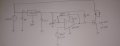
I'm getting from a Hall Effect magnetic sensor a variable voltage between 0.8 and 3V. When the voltage is around 0.8-0.9V, I want to activate a solenoid valve. If the voltage goes more than 1V, the valve should be off. So I thought of an inverting comparator like shown below. For the voltage threshold, I will put a precision pot to carefully adjust it to let's say 1V. The valve is 24V, and less than 1A. I don't have the exact current rating now. My question is: Is this the circuit idea yo would choose for this application? I mean, is there a better way? I'm actually looking for a fast prototype. No worth spending much time on this. So this is the basic idea I came up.

I'm getting from a Hall Effect magnetic sensor a variable voltage between 0.8 and 3V. When the voltage is around 0.8-0.9V, I want to activate a solenoid valve. If the voltage goes more than 1V, the valve should be off. So I thought of an inverting comparator like shown below. For the voltage threshold, I will put a precision pot to carefully adjust it to let's say 1V. The valve is 24V, and less than 1A. I don't have the exact current rating now. My question is: Is this the circuit idea yo would choose for this application? I mean, is there a better way? I'm actually looking for a fast prototype. No worth spending much time on this. So this is the basic idea I came up.