Using a 6-28V 80W DC motor speed controller at 5V ?

Thread Starter

guiguideb

Joined May 29, 2020
11
Hello,

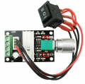
I would like to use this 80W 6-28V 3A DC PWM motor speed controller using my power bank that output 4.9-5.1 V
The problem is that using a bench power supply I can see that the board only works at about 5.6V, is there a way to make it work at 5V ?

The board is based on a NE555 which according to its datasheet can work at 5V.

I'm guessing it doesn't work at 5.3V (I checked using the bench power supply) because maybe one of the resistors/diode drops the voltage a bit, but i'm a newbie so I don't really know.

Is there a way to fix that ? I don't need reverse voltage protection nor 3A, I only need 5V and let's say 2A.
Can I remove/replace a resistor/diode to get it working at 5V ?

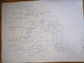
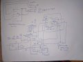
I created the schematic of the board using a multimeter, but don't trust it 100%, I'm sure I forgot/made wrong connections.
If you need infos on particular components that are on the board feel free to ask.

Thank you !

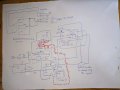
Note : I've circled 2 components in red in the "capture.PGN" file because they don't look like that on my board (the "IMG_20200617_150759.jpg" is taken by me).
 

Attachments

Alec_t

Joined Sep 17, 2013
14,280
If you're only ever going to use the controller with that power bank then you could try just bypassing the 78L05 regulator.
 

Thread Starter

guiguideb

Joined May 29, 2020
11
Thank you for your answers ! It helped me a lot, I indeed forgot a connection, please check "circuit fixed", I added the new connections in green (yes I just realised that one of the green connection is useless since the power mosfet was already connected to ground).

The 78L05 Vout outputs a steady 5V, so I'm guessing I can bypass it like your said, please look at the "regulator bypass" image, did I bypassed it correctly ? I left the C5 capacitor since it's connected between +5V in and ground so I guess it's just like the 35V 220uF capacitor, it helps with voltage spikes/changes regulation ?

But what is the utility of the 78L05 in the first place ? The only thing I can think of is that NE555 Vcc in is 18V max, so they added the regulator so that you can use the board with a 28V power supply.

Thank you again for your help ! I learned a lot by analyzing the diagram.
 

Attachments

Irving

Joined Jan 30, 2016
3,843
Another issue is there may not be enough gate drive for the mosfet below 5v. So it wont turn fully on and could get hot depending on load/pulse width. Datasheet suggests its probably ok..
 

Thread Starter

guiguideb

Joined May 29, 2020
11
Another issue is there may not be enough gate drive for the mosfet below 5v. So it wont turn fully on and could get hot depending on load/pulse width. Datasheet suggests its probably ok..
I guess i'll try
I'm having difficulty following your schematic, but it looks like you've removed the ground connection to the power MOSFET source?
I've removed it because it is already connected to ground, is it correct ?
1593264786032.png
 

Thread Starter

guiguideb

Joined May 29, 2020
11
Then I don't understand :/ Could you please explain me in more details what problem I created by removing the wire ?
 

Irving

Joined Jan 30, 2016
3,843
Is your 'ground' connection the junction to the left of C2? The issue is you use both 'jump over' and 'dotted junction' conventions in your schematic and its very confused. Maybe you should tidy it up, lay it out more conventionally with correct symbols and it might make more sense...

Then people might be able/happy to address your issue rather than than spending time deciphering ypur drawing...
 

Thread Starter

guiguideb

Joined May 29, 2020
11
The issue is you use both 'jump over' and 'dotted junction' conventions in your schematic and its very confused.
I didn't realise that this was the problem thank you
Here is the new schematic, the VCC and RESET pins of the NE555 are connected to 1593431771209.png which mean they're connected to 5V DC.
 

Attachments

Irving

Joined Jan 30, 2016
3,843
Still a mess.... lets tidy up ....

Poof... a few minutes later...

1593437593947.png

Now we can see the wood for the trees.... I've also corrected a couple of errors that were obvious.

A few minutes of effort would have got you much faster, accurate answers. Most people can't be bothered dealing with someone else's mess - if its important to you make it easier for others...

So... IMHO it'll probably work, assuming the motor isn't too noisy an falsely triggers the 555. I'd stick some additional bulk (200uF) and decoupling (100nF) capacitors across from +PWM_to_switch to ground as close to the MOSFET as you can.

Like this:

1593438470762.png
 
Last edited:

Thread Starter

guiguideb

Joined May 29, 2020
11
Thank you very much for your help, it worked ! I didn't realise that my schematic made it harder for you all to help
 
Top