Using 8X8 RGB LED Matrix - Occasionally a row burns out, is there something I'm missing?

Thread Starter

Mahonroy

Joined Oct 21, 2014
417
Just figure out how much current you want in each color LED and then map out how much current each resistor will carry and then determine how much voltage you want to drop across each resistor. Then it's a simple matter of applying Ohm's Law.
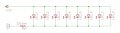
This should be the correct representation of a single column on the 8x8 RGB matrix, is this correct?
ledpanel_question1.jpg

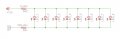
At first I thought this was the representational equivalent of adding a resistor to the row +12v, but quickly realized this is incorrect because this would be in parallel with the other rows......
ledpanel_question2.jpg
This picture directly above is not correct.

So I am actually not sure how to do this? I was shooting for 5mA per LED.
 

dl324

Joined Mar 30, 2015
18,446
So I am actually not sure how to do this? I was shooting for 5mA per LED.
Both schematics reflect what you have or would have if you drove all anodes simultaneously or added a resistor between a row common anode and the supply. You'll never be able to get what you want with this method.

In an earlier post, I incorrectly confirmed your 5mA current with a 200 ohm resistor. It should have been 2K; 10V/5mA = 2K ohms.

Since you're not operating at max DC current, you don't need to worry about the multiplexer stopping and burning out LEDs.
 

Thread Starter

Mahonroy

Joined Oct 21, 2014
417
Both schematics reflect what you have or would have if you drove all anodes simultaneously or added a resistor between a row common anode and the supply. You'll never be able to get what you want with this method.

In an earlier post, I incorrectly confirmed your 5mA current with a 200 ohm resistor. It should have been 2K; 10V/5mA = 2K ohms.

Since you're not operating at max DC current, you don't need to worry about the multiplexer stopping and burning out LEDs.
I am now trying to come up with the solution without using the multiplexer, and just driving all LED's simultaneously. I found the CD4022b which will handle the multiplexing stuff.

So now I am exploring the possibility of driving all LED's simultaneously, and adding in the 8x extra resistors that were discussed earlier on the +12v row side. The 2nd diagram as I mentioned above is not a correct representation of the problem. I am trying to figure out how to choose an appropriate resistor value for those 8x new resistors (making the assumption that all of the LED's are identical - which I know are not - just for the calculations).
 

ronv

Joined Nov 12, 2008
3,770
I am now trying to come up with the solution without using the multiplexer, and just driving all LED's simultaneously. I found the CD4022b which will handle the multiplexing stuff.

So now I am exploring the possibility of driving all LED's simultaneously, and adding in the 8x extra resistors that were discussed earlier on the +12v row side. The 2nd diagram as I mentioned above is not a correct representation of the problem. I am trying to figure out how to choose an appropriate resistor value for those 8x new resistors (making the assumption that all of the LED's are identical - which I know are not - just for the calculations).
Actually with such a low current (5ma) and 8 in parallel, I think you can get away with what you have. If push comes to shove many manufactures bin LEDs by Vf, so you might look at that. Are they standard T1/4 LEDs?
 
Top