Facebook
 Google
 GitHub
 Linkedin
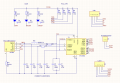
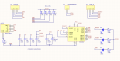
Hello everyone, I'm working on a USB<->UART converter based off FTDI's FT230X(S) IC and would like a bit of input. Right now it is almost done (the schematic, that is), and I attached a picture of it.
I must also say I knew, and still kind of know, next to zero about electronics and electricity in general when I took this project. (sorry for the length in advance, couldn't really keep it both short and complete at the same time)
I'll be using a micro-USB port, so 5 "input" signals (with a header in parallel, which was asked of me, not entirely sure why). Everything is SMT. Here's what's what:
-UART "Output" is connected to a second header with data flow, ground and 3v3/5v;
-I also included output reading of CTS/RTS for hardware handshaking;
-I include three LEDs, two for data transmission/reception detection (TXLED/RXLED pulse low when data is transmitted/received), and one for power detection;
-I include a set of pull-ups to set the default logic levels;
-I include a 0-value resistor to act as a fuse for the USB shielding. This was a hint from a friend of mine who happens to work in this area.
Now for my doubts. As I said, I'm not very electronics-savvy, so kind of bear with me:
-First off, does anything jump out as blatantly wrong in the schematic?
-Second, is the bottom LED well designed? It should shine to indicate the board is connected and powered;
-Third, how exactly do I go about the fuse resistor in terms of PCB layout? Is it just a regular 0 Ohms resistor? My question is how exactly do I know what to use for this particular matter.This was a hint from a friend of mine who happens to work in this area. How exactly do I go about this in terms of PCB? Is it just a regular 0 Ohms resistor? My question is how exactly do I know what to use for this particular matter.
-Fourth, is it a good asset to have both 3V3 and 5V on the UART-side header? I did this so that, when connecting to that header, you'd have the chance of working in different voltages. Is it worth it, or should I just leave one of them there? Which, in that case? (I'm guessing it depends on what I'm using the board for)
-Fifth, the schematic off of which I based mine the most (an official one by FTDI) had a "ferrite bead" between the USB's 5V output and what I label as VCC. Hence the two VCC-Cap-GND structures you see on my schematic (on the FTDI schematic, one was between the USB plug and the bead, and the other one, labelled VCC, after the bead and into the IC). Thing is, as far as I know, these beads don't go into a PCB - they refer to beads in the cables, in this case the USB one. As such, should I erase one of the VCC-Cap-GND structures? If so, which? I'm trying to understand how capacitors smooth the current to the point of figuring this one out by myself, but still no luck.
-The TXLED/RXLED are configured by default to pulse low when there is data transmission/reception. Just how do those LEDs glow in those circumstances? I know the schematic is right in that aspect since it was the same in the FTDI one.
Thanks for the help in advance, I'm having a hard time conciliating this project with my exams right now.
Link to the IC I'm using:
http://www.ftdichip.com/Support/Documents/DataSheets/ICs/DS_FT230X.pdf
I must also say I knew, and still kind of know, next to zero about electronics and electricity in general when I took this project. (sorry for the length in advance, couldn't really keep it both short and complete at the same time)
I'll be using a micro-USB port, so 5 "input" signals (with a header in parallel, which was asked of me, not entirely sure why). Everything is SMT. Here's what's what:
-UART "Output" is connected to a second header with data flow, ground and 3v3/5v;
-I also included output reading of CTS/RTS for hardware handshaking;
-I include three LEDs, two for data transmission/reception detection (TXLED/RXLED pulse low when data is transmitted/received), and one for power detection;
-I include a set of pull-ups to set the default logic levels;
-I include a 0-value resistor to act as a fuse for the USB shielding. This was a hint from a friend of mine who happens to work in this area.
Now for my doubts. As I said, I'm not very electronics-savvy, so kind of bear with me:
-First off, does anything jump out as blatantly wrong in the schematic?
-Second, is the bottom LED well designed? It should shine to indicate the board is connected and powered;
-Third, how exactly do I go about the fuse resistor in terms of PCB layout? Is it just a regular 0 Ohms resistor? My question is how exactly do I know what to use for this particular matter.This was a hint from a friend of mine who happens to work in this area. How exactly do I go about this in terms of PCB? Is it just a regular 0 Ohms resistor? My question is how exactly do I know what to use for this particular matter.
-Fourth, is it a good asset to have both 3V3 and 5V on the UART-side header? I did this so that, when connecting to that header, you'd have the chance of working in different voltages. Is it worth it, or should I just leave one of them there? Which, in that case? (I'm guessing it depends on what I'm using the board for)
-Fifth, the schematic off of which I based mine the most (an official one by FTDI) had a "ferrite bead" between the USB's 5V output and what I label as VCC. Hence the two VCC-Cap-GND structures you see on my schematic (on the FTDI schematic, one was between the USB plug and the bead, and the other one, labelled VCC, after the bead and into the IC). Thing is, as far as I know, these beads don't go into a PCB - they refer to beads in the cables, in this case the USB one. As such, should I erase one of the VCC-Cap-GND structures? If so, which? I'm trying to understand how capacitors smooth the current to the point of figuring this one out by myself, but still no luck.
-The TXLED/RXLED are configured by default to pulse low when there is data transmission/reception. Just how do those LEDs glow in those circumstances? I know the schematic is right in that aspect since it was the same in the FTDI one.
Thanks for the help in advance, I'm having a hard time conciliating this project with my exams right now.
Link to the IC I'm using:
http://www.ftdichip.com/Support/Documents/DataSheets/ICs/DS_FT230X.pdf
Attachments
-
 117.9 KB Views: 79