
Hi, I made this USB to RS485 Conveter and have been trying to get it to work but have had little success. Wondering if anyone can help me out?
I have been communicating with a PID controller using an off the shelf USB to RS485 converter and thought it would be fun to try to make my own.
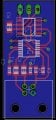
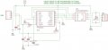
The circuit uses the FT230X and MAX13082, as far as I can tell I have the schematic correct and have the FT230X programmed correctly. Using a scope I can see that there is information being sent and that the levels appear correct compared to the off the shelf version but I don't have a scope that can read the info being sent.
The schematic I used is basically right from the FT230X datasheet. I omitted the pull up resistors but have since tried adding them in but that did not change anything.
Any help/ideas would be appreciated
I have been communicating with a PID controller using an off the shelf USB to RS485 converter and thought it would be fun to try to make my own.
The circuit uses the FT230X and MAX13082, as far as I can tell I have the schematic correct and have the FT230X programmed correctly. Using a scope I can see that there is information being sent and that the levels appear correct compared to the off the shelf version but I don't have a scope that can read the info being sent.
The schematic I used is basically right from the FT230X datasheet. I omitted the pull up resistors but have since tried adding them in but that did not change anything.
Any help/ideas would be appreciated
Attachments
-
 28.8 KB Views: 20
 -
 76.2 KB Views: 24


