Facebook
 Google
 GitHub
 Linkedin
Hi,
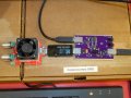
I wanted to talk about this new project, and show some photos. It is a USB test switch, or switcher, aimed for test automation. Basically, it allows you to connect or disconnect the bus power or the data lines separately, for enumeration testing.
For now, you can see a photo of the board, and the schematic. I'll post more details soon. I'm still designing the circuit, since this project is still a prototype. Many things were already green wired onto the board, in order to fix the current measurement glitch. Also, forgot to add a pull-up resistor to an open collector output.

Anyway, this board employs a TS3USB221A to connect and disconnect the data lines. For interrupting Vbus, I've used a LM3525-H. Originally, a LM3525-L was used, but then I've verified that Vbus would connect when the USB on the control side was disconnected. The solution was to use the "H" version instead, with its "EN" input negated via a transistor.
I'm yet to characterize the board, and also create software and drivers. Anyway, I just wanted to share this with you.
Kind regards, Samuel Lourenço
I wanted to talk about this new project, and show some photos. It is a USB test switch, or switcher, aimed for test automation. Basically, it allows you to connect or disconnect the bus power or the data lines separately, for enumeration testing.
For now, you can see a photo of the board, and the schematic. I'll post more details soon. I'm still designing the circuit, since this project is still a prototype. Many things were already green wired onto the board, in order to fix the current measurement glitch. Also, forgot to add a pull-up resistor to an open collector output.
Anyway, this board employs a TS3USB221A to connect and disconnect the data lines. For interrupting Vbus, I've used a LM3525-H. Originally, a LM3525-L was used, but then I've verified that Vbus would connect when the USB on the control side was disconnected. The solution was to use the "H" version instead, with its "EN" input negated via a transistor.
I'm yet to characterize the board, and also create software and drivers. Anyway, I just wanted to share this with you.
Kind regards, Samuel Lourenço