
 Facebook
 Google
 GitHub
 Linkedin
Hi!
I'm a student in electric engineering, for my internship my employer requested me to make an USB sniffer. I've been keyboard-jockeying for days now, looking at datasheets, specifications and models.
A short introduction for the ones who are not so familiar with USB.
USB has four wires: gorund, Vbus, D- and D+.
De data is provider bij D- and D+. The differential of the two respresents the data. The data is encoded with NRZI. A 0 will make the signal flip sign and a 1 will keep the same signal level. If a 6bits of 1 are sended an additional 7th bit (0) is send to make the signal flip. Adding this dummy bit is called bit-stuffing and is used to keep the clocks of the host and client in sync. The clocks are generated from the data signal.
When the signal is received the NRZI is decoded and bitstuffing removed. Then the controller will detect the USB pakket start (start with a synac field). The packets are buffers which are called endpoints.
CRC is applied to the packets to maintain data integrity. When an error is detected this will be flagged and the corrupt packet will be discarded.
From the endpoints on the software will take over. The software will address the Host Controller Interface. They used to be of type OHCI or UHCI, but nowadays EHCI is used. All modern operating systems come with a Host Controller Driver (most of the time in the kernel).
De the USB host (master) always start with communicating when it detects a newly connected device by measurement of voltage/impedance. The USB host sends the client a request to indentify itself, this information is called the USB descriptors. Then normal data transfer can proceed.
Linux Kernel 2.6 will write the descriptors to "/proc/bus/input/devices" en the data to "/dev/xxx", where xxx represents the device.
The customer would like informatie of all levels of the USB-connection (a bit similar to the OSI model).
A. Physical (electrical signals)
B. The bitstream (which is just the differential between D- and D+)
C. The USB packets
D. The USB descriptors and the USB data
The goal is that the measurement is done on the kabel between the host and the client (like a pc and mouse).
A PCB for this purpose could look like this:

Or like this:

Because of the limited time and the complexcity of an USB controller i'd rather not design one myself. But i do want the packets which are usually discarded by regular USB controllers. Usually only a flag is set when a corrupt packet is detected, but it doesn't indicate in which bit the error was found.
The idea is now to connect an USB controller as well as an USB probe to the probing-point
This would look like this:
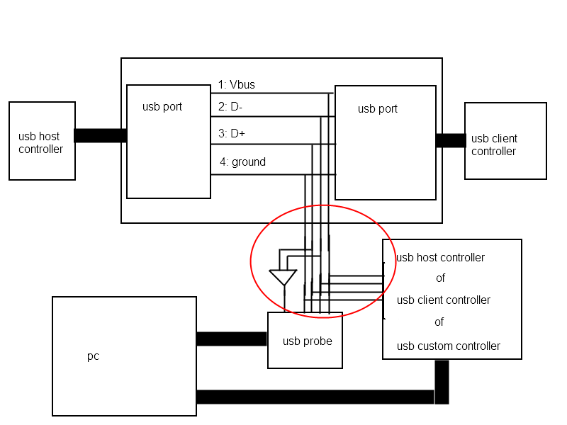
The USB probe is supposed to gather information about A, B and C. The controller about C and D.
I assume the USB probe won't drain too much current because of the high input-impedance. But i expect the usb controller to drain a significant amount and mess up the signal. So i need some kind of analog buffer that preserves the signal. I was thinking in the direction of operational amplifiers. This should go somewhere in the area located with the red circle.
Additional information:
* I would like to support USB 1.0 (low-speed), USB 1.1 (full-speed) and USB 2.0 (high-speed).
* The USB probe would be a osciloscope with USB interface and without display. I haven't investigated yet if there are USB scopes/probes with a sample rate high enough for 480 Mbit/s
My question is: am i going the right way with my solution?
Especially about the analog part (red circle), but any suggestions or comments are very welcome!
Thanks!
I'm a student in electric engineering, for my internship my employer requested me to make an USB sniffer. I've been keyboard-jockeying for days now, looking at datasheets, specifications and models.
A short introduction for the ones who are not so familiar with USB.
USB has four wires: gorund, Vbus, D- and D+.
De data is provider bij D- and D+. The differential of the two respresents the data. The data is encoded with NRZI. A 0 will make the signal flip sign and a 1 will keep the same signal level. If a 6bits of 1 are sended an additional 7th bit (0) is send to make the signal flip. Adding this dummy bit is called bit-stuffing and is used to keep the clocks of the host and client in sync. The clocks are generated from the data signal.
When the signal is received the NRZI is decoded and bitstuffing removed. Then the controller will detect the USB pakket start (start with a synac field). The packets are buffers which are called endpoints.
CRC is applied to the packets to maintain data integrity. When an error is detected this will be flagged and the corrupt packet will be discarded.
From the endpoints on the software will take over. The software will address the Host Controller Interface. They used to be of type OHCI or UHCI, but nowadays EHCI is used. All modern operating systems come with a Host Controller Driver (most of the time in the kernel).
De the USB host (master) always start with communicating when it detects a newly connected device by measurement of voltage/impedance. The USB host sends the client a request to indentify itself, this information is called the USB descriptors. Then normal data transfer can proceed.
Linux Kernel 2.6 will write the descriptors to "/proc/bus/input/devices" en the data to "/dev/xxx", where xxx represents the device.
The customer would like informatie of all levels of the USB-connection (a bit similar to the OSI model).
A. Physical (electrical signals)
B. The bitstream (which is just the differential between D- and D+)
C. The USB packets
D. The USB descriptors and the USB data
The goal is that the measurement is done on the kabel between the host and the client (like a pc and mouse).
A PCB for this purpose could look like this:
Or like this:
Because of the limited time and the complexcity of an USB controller i'd rather not design one myself. But i do want the packets which are usually discarded by regular USB controllers. Usually only a flag is set when a corrupt packet is detected, but it doesn't indicate in which bit the error was found.
The idea is now to connect an USB controller as well as an USB probe to the probing-point
This would look like this:
The USB probe is supposed to gather information about A, B and C. The controller about C and D.
I assume the USB probe won't drain too much current because of the high input-impedance. But i expect the usb controller to drain a significant amount and mess up the signal. So i need some kind of analog buffer that preserves the signal. I was thinking in the direction of operational amplifiers. This should go somewhere in the area located with the red circle.
Additional information:
* I would like to support USB 1.0 (low-speed), USB 1.1 (full-speed) and USB 2.0 (high-speed).
* The USB probe would be a osciloscope with USB interface and without display. I haven't investigated yet if there are USB scopes/probes with a sample rate high enough for 480 Mbit/s
My question is: am i going the right way with my solution?
Especially about the analog part (red circle), but any suggestions or comments are very welcome!
Thanks!






