Facebook
 Google
 GitHub
 Linkedin
Hey all,
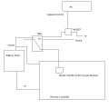
I am trying to control an RC car from my computer via a USB device. The USB interface I am using is this one.
I have already written all the code for it (host and device). I am setting four different output pins to high based on user input at the PC.
I have also taken apart the RC Car's remote and found the switches that control forward/backward/left/right. I have been able to short-circuit the switches using relays on a breadboard, and I can control the remote by turning the relays on/off.
However, since my background is entirely in software, I am not very confident about hooking up my breadboard circuit to the PIC on the USB device. The breadboard circuit has a wire attached to the RC switch for a direction and that wire is grounded when the relay is powered. It works, but I'm not sure if I am slowly frying all the circuits involved.
The current relays are 56 ohm coils with a nominal voltage of 5. From what I remember from Physics E/M that's 89 mA of current. The PIC output pins can only drive 25 mA (I believe). So I don't think my existing breadboard circuit is safe for the PIC. No other relays were available at RadioShack, but I found this one online. It seems like it would only pull 12.5 mA of current.
I am looking for some confirmation or words of experience concerning having a PIC's output pins drive relays and how to prevent everything from burning. Also, I'm pretty new to the hardware side of things, so any details are appreciated.
Thanks!
-Andrew
")