Unstable DC voltage output from DC-DC Boost

Thread Starter

Z'YonG

Joined Feb 2, 2017
63
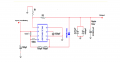
Hi guys, I have built a DC-DC Boost circuit with MC33063AP. The schematic is as shown below:

upload_2017-7-24_10-56-27.png

My R1 is 11K, and R2 is 330K, according to the equation Vout=1.25*(1+R2/R1), it should give me 38.75V, but instead of that, it gives me 36.8V. 36.8V is fine as well, because I have replaced two of the inductors into one 220uH inductor, and also the last three capacitors into one 470uF capacitor. However, I have found out the voltage is not stable, from the oscilloscope, I can see the voltage is jumping between 3 figures: 36.4V, 36.8V and 37.2V…

Does anyone knows why? I am thinking that it is from the capacitor charge and discharge, but I am not sure how to fix it.

Thank you!
 

Attachments

bertus

Joined Apr 5, 2008
22,266
Hello,

Your schematic looks close to the schematic in the datasheet of TI:

MC33063A_boost_info.png
MC33063A_boost_calculations.png

The datasheet tells me that a ripple of 400 mV is normal.
You got 800 mV ripple.

Is the measurement taken with a load?
Switchmode supplies can have troubles when there is no load.
What is your intentional maximum load?

Bertus
 

Thread Starter

Z'YonG

Joined Feb 2, 2017
63
As the ripple depends on the load? Do you look at the oscilloscope without load?
I do not see this "jumping" of voltage.
Hello,

Your schematic looks close to the schematic in the datasheet of TI:

View attachment 131811
View attachment 131812

The datasheet tells me that a ripple of 400 mV is normal.
You got 800 mV ripple.

Is the measurement taken with a load?
Switchmode supplies can have troubles when there is no load.
What is your intentional maximum load?

Bertus

Sorry for the late reply.

I did the measurement both with and without the load, the results are the same. My schematic was based on the datasheet. From the oscilloscope, I can see that, some time the ripple is 400mV, and sometime is 800mV... I am not quite sure why...
after the DC DC Converter, I connected it through a 330 ohms resistor to the a transistor, in order to amplify my PWM signal.
 

GopherT

Joined Nov 23, 2012
8,009
Sorry for the late reply.

I did the measurement both with and without the load, the results are the same. My schematic was based on the datasheet. From the oscilloscope, I can see that, some time the ripple is 400mV, and sometime is 800mV... I am not quite sure why...
after the DC DC Converter, I connected it through a 330 ohms resistor to the a transistor, in order to amplify my PWM signal.
Your load is only 36mA in the on-state of your PWM. The circuit is rated at 400 mV regulation at 175 mA. Your low draw is screwing up the circuit's ability to regulate. On top of that, the PWM draws zero current when in low state which makes the circuit even less appropriate.

You need to add a bit of a dummy load (not an efficient solution for a battery powered circuit), or you need a better chip than the MC33063. Look for a better (modern) chip, one that can do pulse skipping for low duty cycle output.
 

jtn

Joined Mar 27, 2017
22
For Inductor, try using only one 200uH. For output capacitor, use low ESR capacitor such as MLC type. Boost converter has RHP zero and could cause instability
 
Top