Facebook
 Google
 GitHub
 Linkedin
hello everyone
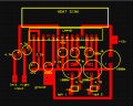
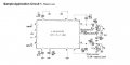
I have made an amplifier circuit based on LA4440 IC according to the datasheet sample circuit. In my circuit I haven't made separate terminals for audio ground & the negative power supply terminal and the circuit works fine. I just want to know that is this the right thing to do, also I couldn't understand which one is the negative voltage supply & ground terminal by looking at the equivalent circuit block diagram from the datasheet. so could anyone help me out?? circuit diagram & equivalent block diagram is attached with the post.
I have made an amplifier circuit based on LA4440 IC according to the datasheet sample circuit. In my circuit I haven't made separate terminals for audio ground & the negative power supply terminal and the circuit works fine. I just want to know that is this the right thing to do, also I couldn't understand which one is the negative voltage supply & ground terminal by looking at the equivalent circuit block diagram from the datasheet. so could anyone help me out?? circuit diagram & equivalent block diagram is attached with the post.
Attachments
-
 38.1 KB Views: 11
 -
 55.8 KB Views: 10