UC3842/3 Compensation Feedback

Thread Starter

SAM-Mo

Joined Jan 19, 2019
42
Hi,

I want to design a Flyback, no problem with the transformer, Clamp .. etc. Now I want to design the feedback circuit using a TL431 and an Optocoupler.

1) How to calculate the Feedback component values for the UC3842/3?
2) How to regulate several outputs?
 

Dodgydave

Joined Jun 22, 2012
11,395
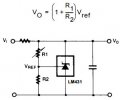
Using the TL431 formula, Vout =( R1/R2) +1 X 2.5V, where R1 is the top resistor, R2 is the bottom resistor.

So if you want 7.5V out, then, R1 can be 10k, R2 5K, etc...

lm431c.jpg
 

Thread Starter

SAM-Mo

Joined Jan 19, 2019
42
Thanks, but it is not that easy as you described. this feedback should run an optocoupler and in harmony with the chip
 

Dodgydave

Joined Jun 22, 2012
11,395
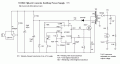
Then download the datasheet for that chip, and it will have a test circuit,, here is one from the internet using an Opto-coupler..
R1 is 39K, R2 8K2, with these values that's 14V.
UC3842 Flyback Converter.gif
 
Last edited:

Thread Starter

SAM-Mo

Joined Jan 19, 2019
42
No, I meant in your mentioned circuit, the input voltage is 12V but your calculations show 14 for the output. therefore it can not be correct for this purpose and feedback design is more complex
 
Top