Facebook
 Google
 GitHub
 Linkedin
It is not sensible to use either Ea or Eb as the reference vector here.
Second you have completely ignored my pointer about the reactance of the machines, so your phasor diagrams do not show these.
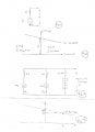
Thre is one current I, circulating in the loop and one Voltage, V common to both branches, each containing a machine and its associated impedance. The impedance, Z, is made up of the resistance R and the reactance X
Thus Z = R + jX:
Both I and V are comples quantities and I have shown them bold to emphasise this. They have a fixed phase relationship, \(\phi\). Since we are talking rotating machinery, the current will be lagging by this angle and X will never be insignificant.
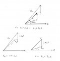
I have shown the combined phasor diagram for this situation and also split it into machine A and machine B. This presentation makes things easier to see.
Note
that the vectors V and I are common to all three diagrams,
that Ea>V>Eb
that Ea leads V and Eb lags V
I have chosen the circulating current as the common baseline
Second you have completely ignored my pointer about the reactance of the machines, so your phasor diagrams do not show these.
Thre is one current I, circulating in the loop and one Voltage, V common to both branches, each containing a machine and its associated impedance. The impedance, Z, is made up of the resistance R and the reactance X
Thus Z = R + jX:
Both I and V are comples quantities and I have shown them bold to emphasise this. They have a fixed phase relationship, \(\phi\). Since we are talking rotating machinery, the current will be lagging by this angle and X will never be insignificant.
I have shown the combined phasor diagram for this situation and also split it into machine A and machine B. This presentation makes things easier to see.
Note
that the vectors V and I are common to all three diagrams,
that Ea>V>Eb
that Ea leads V and Eb lags V
I have chosen the circulating current as the common baseline
Attachments
-
 26.7 KB Views: 13
")