The 741 is a really crappy part to use for an oscillator because it has a seriously limited bandwidth and slew rate.
Starting an oscillator requires parasitic elements or some source of noise to kick things off
I've never seen oscillators with switches. What is their purpose?
What frequency are you aiming for?
Here is an example of a Twin Tee using a noise source to start up. The TL072 has much better bandwidth and slew rate characteristics than the 741, even for such a low frequency. Even so it takes a while for the oscillations to build up as you can see.
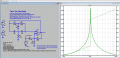
In the simulation posted in #2, the curious comment about "...C6 = 1046.5 Hz." caused me to wonder where the circuit and those values came from. the answer is the Okawa Electric design tools page at http://sim.okawa-denshi.jp/en/TwinTCRtool.php
The use of equal value capacitors has not been treated in any textbook or other source that I have seen recently. Doing an AC analysis on the circuit has allowed pinpointing the center frequency by measuring the width of a very small band around the point of maximum magnitude. It also show how to use TRIG and TARG in a .meas statement
You can also try skipping the initial operating point solution using a uic command, which may work.
The initial operating point calculates the quiescent DC bias condition, which can leave the circuit in a quasi-stable state with no oscillation, since the ideal circuit has no intrinsic noise to start the oscillation.
@crutschow Never mind the following, your comment was a response to post #2, but it still might be useful information. I'll try the uic on the transient simulation
The uic is part of .tran
For the AC analysis the two .option statements skip the parts that fail:
.option noopiter ; skips the newton iteration, and goes directly to gmin stepping
.option gminsteps=0 ; skips gmin stepping
As a result of those two choices, the error log shows:
Direct Newton iteration for .op point skipped.
Gmin stepping method for .op point skipped.
Starting source stepping with srcstepmethod=0
Source Step = 3.0303%
Source Step = 33.3333%
Source Step = 63.6364%
Source Step = 93.9394%
Source stepping succeeded in finding the operating point.
temp: MAX(mag(v(vo)))=(53.0425dB,0°) FROM 100 TO 10000
bw=0.00660821 FROM 1051.91 TO 1051.91
Date: Mon Jan 17 17:27:18 2022
Total elapsed time: 0.078 seconds.
You can also try skipping the initial operating point solution using a uic command, which may work.
The initial operating point calculates the quiescent DC bias condition, which can leave the circuit in a quasi-stable state with no oscillation, since the ideal circuit has no intrinsic noise to start the oscillation.
The uic addition to the .tran command does not seem to have much effect on the startup time of the Twin Tee oscillator. Increasing the magnitude of the noise source does speed things up a bit.
Hello. I'm trying to simulate a twin T Oscillator using TINA. For some reason I can't succeed to create oscillation.Any thoughts? View attachment 257834
I strongly suggest you cut your losses immediately on using TINA. Few people seem to use it and you should bite tue bullet and just get used to the backwards GUI for power placement of LTSpice. I believe the same "engine" drives both but the models of each part seem to be more portable with LTSpice and the parameter adjustments seem to be more obvious vs TINA. Pluses and minuses to each but, TINA usage seems to be low.
IMHO, this is not a supportable proposition. If you look at the development timeline of LTspice, it may have started from the same place but has diverged significantly in the last two decades.
From the wiki: Although LTspice was originally based upon Berkeley SPICE 3f5 source code,[1] it no longer is, thus some of its features may create non-portable files. Competitor SPICE programs have non-portable features too.
LTspice uses an integration method, modified trap, that has the speed and accuracy of trap but without the ringing artifact. Modified trap is a method I invented some years ago and was widely available first in LTspice. To the best of my knowledge, it is the best means to integrate the differential equations of an analog circuit and is not duplicated in any other SPICE program. It is the only method I recommend for circuit design.
Postscript on C6 in post #2. This is actually a reference to the frequency of, the C above, the C above, middle C, on a piano. C6 has a frequency of 1046.5 Hz.
Also it has nothing to do with a non-existent capacitor C6 which does not appear in the circuit. I should leave better notes in my two your old simulation projects.
The 741 is a really crappy part to use for an oscillator because it has a seriously limited bandwidth and slew rate.
Starting an oscillator requires parasitic elements or some source of noise to kick things off
I've never seen oscillators with switches. What is their purpose?
What frequency are you aiming for?
Here is an example of a Twin Tee using a noise source to start up. The TL072 has much better bandwidth and slew rate characteristics than the 741, even for such a low frequency. Even so it takes a while for the oscillations to build up as you can see. View attachment 257835 View attachment 257836 View attachment 257838
Another Twin T oscillator using op amp. It is variable 150 - 330 Hz ( sine wave, small clipping)
Published by Newton C Braga can be found at: http://www.incbtech.com/index.php/circuit-bench/601-twin-t-oscillator-using-the-741-msb034
What I liked about Braga's oscillator is that in trying to develop a frequency range we can mess with the two resistor values (22k)
could be 23k but too much resistance will impede the startup. Using the calculator page listed above PapaBravo post #3 more possibilities being able to easily find the right component values.
My low voltage Twin T is a sine wave fixed at 747Hz with a startup time about 12ms, it uses momentary switch as a keyer (price of tactile momentary are very low right now) it can also be used as a portable audio source for trouble shooting. I made it on an early version of EWB electronic work bench very long ago so please excuse using the wrong switch and output capacitor. I probably got the idea for this circuit from an old ham radio magazine and liked it's simplicity. A voltage follower can improve output and I also used a 1:3 diy transformer raise the voltage so it would light an led.
 Facebook
 Google
 GitHub
 Linkedin