 Facebook
 Google
 GitHub
 Linkedin
Hi
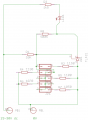
Have this setup .
Use of a TL431
When voltage is over fixed value, ex 24,24V then LED is on, and off again at 23,81 V
when changed from JUMPER 1-5 i can select different voltages to on/off
Use of 5 different resistors from 1050 - 1070 -1100 - 1130 -1150 Ohm
Gives me a on/off voltage from
On 24,24v off 23,81v
On 24,62v off 24,19v
On 25,23v off 24,78v
On 25,86v off 25,41v
On 26,31v off 25,84v
These values is ok for me,
I just want to know if this will work IRL,
Attachments
-
 18.5 KB Views: 42


 I misread your post #3.


