 Facebook
 Google
 GitHub
 Linkedin
Hello everyone, im pretty new at electronics so if this is a dumb question please explain it to me.
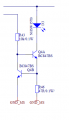
Im trying to understand this power source circuit, my only problem is that I dont really understand it. Why are there 2 transistors and where are those 2 resistors for? All I know is that its supposed to be a power source for an individual LED.
I hope anyone can help me, would be appreciated!
Im trying to understand this power source circuit, my only problem is that I dont really understand it. Why are there 2 transistors and where are those 2 resistors for? All I know is that its supposed to be a power source for an individual LED.
I hope anyone can help me, would be appreciated!
Attachments
-
 9.3 KB Views: 39


