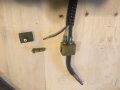
so there it is. If you reread my posts I think you will understand what I'm dealing with here. UPDATE: I have ordered a 120v solenoid to add to the welder. I'm trying to spend as little as possible, in case the whole thing ends up in the dumpster.
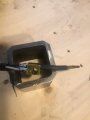
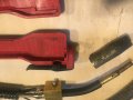
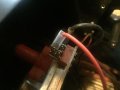
so back to the pictures. you can see the brass button. that fits under the trigger on the whip/stinger (same thing). there should be a spring to return the button, but it is missing. Possibly gone to rust while living in an unheated shed for decades! if you look at other pictures you can see the o-rings on the button and the precision bores in the "block". the o-rins operate the gas valve. button fully up, no gas flow. button down, gas flow and wire feed motor turned on. the valve is dead simple. So, the whip contains the following: 1) the tube that carries the weld wire 2) the white tube is for gas 3) a power cord to carry the weld current 4) a fine wire that goes back to the welder to turn on the wire feed drive motor.
This fine wire had me going for a while. It's (seems to be) attached to the same conductive block as the weld wire. the bottom of the brass button would make contact with the otherwise insulated screw terminal on that flat piece of black plastic. That plastic seals the bottom of the bore in the block and holds the terminal to take the signal back to the drive motor. But anyway, it works.
And I just remembered the electric solenoid. More picturs to come.
OK, creating the mount for a switch will be a mechanical challenge, probably the biggest one. The thinner wire is for the wire feed control, with the return being the weld power conductor. So you may need to do a bit of machining. It may even work better to have the switch located elsewhere. Worst case would be to have a foot operated foot switch and not use any control on the torch part. Depending on your working style that may be a good choice, really.
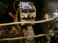
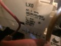
So here are pictures of the solenoid that clicks when the feed motor is activated. the second picture shows what is printed on the side of said solenoid. I didn't get a good picture of it, but the green connector going into the top of the solenoid says 110v. The last picture is of the connectors at the top of the wire feed speed control boardrd.
All I need (I think) is a switch [normally open] in place of the trigger. I already have many such switches from salvage work on various gadgets. And if it works, I can slave off the 110v that switches the solenoid at the same time as the feed motor, and run it to the gas solenoid (110v) and I should have a welder that looks and works more like 2020 than 1980. Cross your fingers. Oh wait, that's superstitious. My bad.
Thanks to all for your interest and help! My gas solenoid isn't here yet, but I will put up my results...eventually.
All I need (I think) is a switch [normally open] in place of the trigger. I already have many such switches from salvage work on various gadgets. And if it works, I can slave off the 110v that switches the solenoid at the same time as the feed motor, and run it to the gas solenoid (110v) and I should have a welder that looks and works more like 2020 than 1980. Cross your fingers. Oh wait, that's superstitious. My bad.
Thanks to all for your interest and help! My gas solenoid isn't here yet, but I will put up my results...eventually.
OK, creating the mount for a switch will be a mechanical challenge, probably the biggest one. The thinner wire is for the wire feed control, with the return being the weld power conductor. So you may need to do a bit of machining. It may even work better to have the switch located elsewhere. Worst case would be to have a foot operated foot switch and not use any control on the torch part. Depending on your working style that may be a good choice, really.
Thanks for the photos of the stinger, never saw or heard of one like that. With the valve in it I can't see the need for a solenoid valve, and have my doubts now that it ever had one. As long as you can mke the switch work to energize the wire feeder, you should be good to go, until the stinger dies. When that would happen you will need a solenoid valve for the gas. The switch and wire in the stinger handle is all any I've ever used or seen have and there is a wire in the sheath that does control both the wire feed and gas.
OK, the pictures give all of the information except for the brand of the device. It is a 4-pole normally open contactor, with some interesting adapters to put all 4 poles in parallel. Each pole is rated at only 30 amps and so that is why the adapters. They tend to keep the current split equally. It would be a good idea to verify that all of the connection screws are still snug, because a loose screw will prevent equal current distribution. Unfortunately none of the pictures give a good view of the screws that I am talking about, They are down inside fairly deep holes, a total of 8, 4 on each side.
I have seen (I think) 4 of the screws, and your correct, they are buried. It looks like checking that will require removal of the contactor. And possibly some disassembly of the contactor.
Thanks for the photos of the stinger, never saw or heard of one like that. With the valve in it I can't see the need for a solenoid valve, and have my doubts now that it ever had one. As long as you can mke the switch work to energize the wire feeder, you should be good to go, until the stinger dies. When that would happen you will need a solenoid valve for the gas. The switch and wire in the stinger handle is all any I've ever used or seen have and there is a wire in the sheath that does control both the wire feed and gas.
I have seen (I think) 4 of the screws, and your correct, they are buried. It looks like checking that will require removal of the contactor. And possibly some disassembly of the contactor.
You should be able to just insert a screwdriver and verify the torque. But careful to not ise a tapered driver that hits the sides of that deep cavity.
And if the valve leaks a bit you can still use it, along with a solenoid valve at the feed point, to keep the line full of gas. That will improve the response time and also save gas. A new spring for the valve and probably a new "O" ring and a bit of silicone grease should make it work very well. And often those "old relics" are built far better than the current crop of equipment. Not as many features, but built to last for many years.
If true you can still use it as a flux core. Many people don't like flux core and put it down, but I don't understand why. Other than chipping a little slag, much less than stick welding, the welds are just as strong as MIG, and really less splatter than I get from MIG. The strength of any weld is from technique and the wire grade, flux and MIG mostly have the same E number.

 Facebook
 Google
 GitHub
 Linkedin