Facebook
 Google
 GitHub
 Linkedin
Hi,
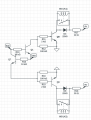
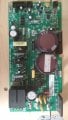
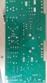
I have a MC2100ELS-18W (rev -) motor controller from a treadmill that I am trying to repair. I don't have the console that was used in the treadmill so I'm currently trying to control it from an Arduino Uno. The board looks OK, no traces of burnt component ( very slightly darker on one pin of the flyback diode and the IGBT).
First, when I plug the board to the 220AC (Europe), the STR component (W6251) make noise and the LED is solid red.
Then, when I input a PWM signal to the board with the arduino (5V 50ms period square signal according to what I've found about the MC-2100 and other sources), my motor have an impuls without really starting. Without a motor connected or with a small one (500W) the led then blinks twice every 15sec or so, with a bigger motor (130V DC, 2.8HP) the led would blink 4 times in 15sec. The measured voltage without a motor are the following : 15V without PWM signal, it reach 70V when I send a signal and then slowly decrease to 13-15V (capacitors discharging ?) .
There is also a problem with the incline motor command : when I apply 5V to the down command , nothing happens, however if I measure voltage (with a multimeter) between the up command and GND at the same time, the down relay activate, I measure 4.3V at the up command and the STR noise stop.
I've already replaced the STR but it doesn't change anything so I'm looking for anyone that could help me having any input about my problems.
I attached two pictures of the board
Thank you for your help and sorry for my english, it's not my mother tongue.
Henri H.
Attachments
-
 136.8 KB Views: 78
 -
 116.7 KB Views: 71
")