Facebook
 Google
 GitHub
 Linkedin
Hello AAC Universe,
This is my first post on here so please forgive any manners that I've yet to learn. I'm in the middle of a power electronics project and have taken a respite to study phase shifting TRIAC circuits so I can use them in my new designs. I have a good grasp of the circuit design and how to snub things for motor control but keep coming across two things in standard off-the-shelf designs that I don't understand:
1) The designs often show the capacitor between the gate and the anode instead of between the gate and the cathode. It's almost like they swap the capacitor and resistor locations. This complicates things in my mind. Why would they do this? Is it functionally different?
2) A full-wave bridge rectifier keeps showing up in the designs and I can't figure out what it's for. Are they just using it as a diode array? Is it some kind of feedback system?
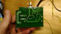
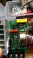
The "off-the-shelf designs" I speak of are eBay purchases which often go by the name of "Dimmer Circuit" or "Power Regulator". I've included a photo of one such circuit as well as my hand-drawn reverse-engineered schematic of it. Help?
This is my first post on here so please forgive any manners that I've yet to learn. I'm in the middle of a power electronics project and have taken a respite to study phase shifting TRIAC circuits so I can use them in my new designs. I have a good grasp of the circuit design and how to snub things for motor control but keep coming across two things in standard off-the-shelf designs that I don't understand:
1) The designs often show the capacitor between the gate and the anode instead of between the gate and the cathode. It's almost like they swap the capacitor and resistor locations. This complicates things in my mind. Why would they do this? Is it functionally different?
2) A full-wave bridge rectifier keeps showing up in the designs and I can't figure out what it's for. Are they just using it as a diode array? Is it some kind of feedback system?
The "off-the-shelf designs" I speak of are eBay purchases which often go by the name of "Dimmer Circuit" or "Power Regulator". I've included a photo of one such circuit as well as my hand-drawn reverse-engineered schematic of it. Help?
Attachments
-
 314.1 KB Views: 14
 -
 100.2 KB Views: 16