Transient Response of AC Coupled Inverting Amplifier

Thread Starter

Blue_Electronx

Joined Jun 10, 2019
112
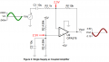
The Circuit 1 attached is from this App Note. The document describes:

The capacitors C1 and C2 need to fully charge for the circuit to function properly. The definition of fully charged can vary depending on the accuracy required for the circuit. If we assume a 12 bit system the time required to fully charge the input capacitors is given below.

For 12 bit settling
τ1 = R1C1 = (1kΩ)(10μF) = 0.01s
T1 = ln(2^N)τ1 = ln(2^12) (0.01s) = 0.083s
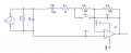
In the second picture, when the switch is open R1 is about 63k. I want to understand better what really happens here when I use this circuit connected to an ADC. In my case I have a 12 bits ADC, so:

τ1 = R1C1 = (63kΩ)(10μF) = 630ms
T1 = ln(2^N)τ1 = ln(2^12) (620 ms) = 5.24s

5.24s is way too long. Does this mean I wouldn't sample the signal correctly until the capacitor charges in ~5s?
 

Attachments

ronsimpson

Joined Oct 7, 2019
3,037
It looks like you are using a current transformer. Over time the average voltage across a CT is zero. Second circuit, you don't need C18.

I think at power up there will be problems that may take 5 seconds to resolve to 12 bits.
 

Thread Starter

Blue_Electronx

Joined Jun 10, 2019
112
It looks like you are using a current transformer. Over time the average voltage across a CT is zero. Second circuit, you don't need C18.

I think at power up there will be problems that may take 5 seconds to resolve to 12 bits.
I read that C18 should help provide little or no DC amplification. This is because the input is a DC-biased AC signal and if the gain
stage provides even a small DC amplification the output will saturate.

So is there any chance of getting some sort of DC amplification without C18? Could it help to choose some enhanced or zero drift amplifier and avoid C18?
 

ronsimpson

Joined Oct 7, 2019
3,037
I do not know what is in the red box. I have used this circuit where the red box is 1/2 of the ADC range voltage. Example: Some ADCs work where 0v=0 and 3.3V=FFFh or full scale. If you set "red box" to 1/2 supply then you can read the signal as it goes plus and negative. When CT=0V the output of the amp will be 1/2 supply. This will work with/with_out C18.
1592364719066.png
If you ground the bottom side of CT then you need C18 to remove the 1.65 volts offset.
 
Top