Transformers, current transformation

Thread Starter

PaulEngineer

Joined Dec 21, 2016
217
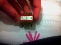
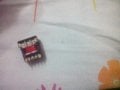
Hello! I was think about that, what is the difference between the common transformer (the transformer on any device that works with AC) and the pulse transformer! And how the pulse transformer looks like? I know how the normal transformer looks like because I have one!

PS I really get confused, there are many types of transformers!
 

Thread Starter

PaulEngineer

Joined Dec 21, 2016
217
For example this transformer in this photo is pulse transformer? (The circuit is from the "EXIT" light that lights up when earthquake or current cutoff, or something like that, happens! It had a fluorescent lamp) If it is not this transformer what kind of transformer is that? Or if it is not a pulse transformer, at least it could be used as pulse transformer? All the answers is helpful!
 

Attachments

LesJones

Joined Jan 8, 2017
4,174
I would not class that as a pulse transformer. It will be a transformer designed to work at high frequency. Probably tens of Khz. It will be part of the step up inverter in the unit that converts the low voltage from a battery to the high voltage for the fluorescent. It will also provide two isolated low voltages to pre heat the filiments in the fluorescent tube. One common use for pulse transformers is to provide isolation between a trigger circuit and the gates of SCRs ot Triacs. They are normall even smaller than the transformer in your picture. Probably smaller than a cube with 20mm sides.

Les.
 

recklessrog

Joined May 23, 2013
985
If you think about it, (loosely speaking) an ignition coil, points and capacitor along with the battery are an example of a "Pulse" transformer.
Igniters in things like boilers, power washers etc often discharge a capacitor into a similar coil to provide enough voltage to create a big spark.
 

recklessrog

Joined May 23, 2013
985
A very simple high voltage spark generator can be made by connecting a 200-300Volt Diac to a capacitor, connect the other end to the primary of an ignition coil, connect the common terminal of the coil to the other end of the capacitor. charge the capacitor from a dc high voltage supply through a fairly high value resistor, and everytime the capacitor voltage reaches the Diac breakdown voltage, the capacitor will discharge into the coil giving a hefty voltage on the HT output lead. always keep something like a spark plug connected to avoid damaging the coil.
 

MrAl

Joined Jun 17, 2014
11,389
Hi again,

Yeah i have to agree a pulse transformer can be a very carefully designed device or just a very simple device that passes what we might call a 'pulse' because a pulse is not a very clearly defined thing. It can be a very rectangular wave or a very rounded wave and still be called a pulse.

The simplest example of a pulse transformer i can think of is using a ferrite bead. Wrap two turns through the center for the primary, two more isolated turns for the secondary, you've got a pulse transformer that can trigger a triac gate long enough to turn it on with the right primary pulse signal.
 
Last edited:

Thread Starter

PaulEngineer

Joined Dec 21, 2016
217
I would not class that as a pulse transformer. It will be a transformer designed to work at high frequency. Probably tens of Khz. It will be part of the step up inverter in the unit that converts the low voltage from a battery to the high voltage for the fluorescent. It will also provide two isolated low voltages to pre heat the filiments in the fluorescent tube. One common use for pulse transformers is to provide isolation between a trigger circuit and the gates of SCRs ot Triacs. They are normall even smaller than the transformer in your picture. Probably smaller than a cube with 20mm sides.

Les.
Wait, wait! If I know well, the transformer cannot work at DC voltage or current! It blocks this voltage but allow AC current! So if it work on a battery power how it possible it work as inverter? And how it increase the DC voltage? Because I know that only the AC current can be able to be changed, I mean to be increased or decreased, am I right? If I said something wrong or I didn't understood a thing, all explanations is helpful :)
 

LesJones

Joined Jan 8, 2017
4,174
What you say is correct that a transformer can only work with AC. There will be a transistor or mosfet that will switch the DC on and off at some high frequency. (A high frequency is used so the transformer can be made smaller.) The AC waveform will not be a sine wave it will be a square wave but the duty cycle may not be 50%. (Depending on the design of the inverter circuit.) In the case of the backup lighting unit you have there will be a battery that is kept charged while the mains supply is present. When the mains supply fails the inverter will step up the voltage from the battery to drive the lamp. Most modern power supplies use this method to reduce the transformer size and cost. The AC input is first rectified to give a DC supply for the inverter. (This DC will be about either 150 or 300 volts depending on the mains voltage.) In this case the inverter circuit is working with this high voltage and the transformer reduces the voltage to the required level. It is then rectified to give the required output. This type of supply normally has a feedback system to control the output voltage by varying the duty cycle of the square wave produced by the inverter. Galvanic isolation of the feedback signal is normally done using an optical coupler. This type of power supply is called a switch mode power supply. ( SMPS)

Les.
 

Thread Starter

PaulEngineer

Joined Dec 21, 2016
217
Oooo thanks!! So, the transformer can work in square waves too? The transformer can work if the current/voltage will be alternated, at least in square wave?
 

Thread Starter

PaulEngineer

Joined Dec 21, 2016
217
What you say is correct that a transformer can only work with AC. There will be a transistor or mosfet that will switch the DC on and off at some high frequency. (A high frequency is used so the transformer can be made smaller.) The AC waveform will not be a sine wave it will be a square wave but the duty cycle may not be 50%. (Depending on the design of the inverter circuit.) In the case of the backup lighting unit you have there will be a battery that is kept charged while the mains supply is present. When the mains supply fails the inverter will step up the voltage from the battery to drive the lamp. Most modern power supplies use this method to reduce the transformer size and cost. The AC input is first rectified to give a DC supply for the inverter. (This DC will be about either 150 or 300 volts depending on the mains voltage.) In this case the inverter circuit is working with this high voltage and the transformer reduces the voltage to the required level. It is then rectified to give the required output. This type of supply normally has a feedback system to control the output voltage by varying the duty cycle of the square wave produced by the inverter. Galvanic isolation of the feedback signal is normally done using an optical coupler. This type of power supply is called a switch mode power supply. ( SMPS)

Les.
Transistor or MOSFET? What is the difference between them? They are both transistors!
 

LesJones

Joined Jan 8, 2017
4,174
The collector to emitter current of a transistor is controlled by the amount of current that passes between the base and emitter. The ratio of these two currents is called the hfe value (Also called beta) The most common mosfet these days is an enhancment type of mosfet. The drain to source current is controlled by the voltage between the source and gate. (For an N type mosfet.) with zero volts between the gate and source there is almost no current flow between source and drain. As the voltage of the gate becomes more positive with respect to the source it gets to a point were the current between drain and source starts to increase. This is call the threashold voltage. As the gate to source voltage is increased from that point the drain to source current increases. There is no current flow between gate and source but there is quite a large capacitance (Can be several nF) between gate and source so in switching applications the driver needs to be able to charge and discharge this capacitance quickly.

Les.
 

LesJones

Joined Jan 8, 2017
4,174
No There is a whole range of BJT and mosfets. You chose the type of device and it's part number that best matches your requirments for a particular application. You may even chose an IGBT which is yet another type of device.
 
Top