 Facebook
 Google
 GitHub
 Linkedin
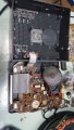
Hello i need help to figure voltages on these wires coming from transformer.The transformer stopped working after rain and thunder then i opened the radio (seen in the picture below) and checked the transformer and i figured that the main HV side of transformer has no continuity when checked with multimeter however the low side of the transformer has continuity.
Yellow and Blue wires have = 31,5 ohm
Yellow and Red wires have = 31,5 ohm
Yellow and Black wires have = 26,3 ohm
Red and Black wires have = 6 ohm
Red and Blue wires have = 11,2 ohm
Black and Blue wires have = 6 ohm
Seem odd that all of the wires are connected together ... i dont know maybe all the coils are blown ? HELP
Attachments
-
 320.9 KB Views: 12
 -
 215.6 KB Views: 13


