 Facebook
 Google
 GitHub
 Linkedin
Hello dear forum.
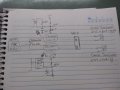
I've been beating my brains out in a circuit I attached a figure below. Well I have 2 current transformers(CT). First from current on secondary 100A:50mA and second from voltage on secondary 100A:1V. In my first CT, I need to add burden resistance to measure current on secondary and add an offset of +2.5V because of my ADS1115 (16 bit ADC) Im going to read on its analog input, however for second CT I just need to add offset. About this circuit its done and you can find more info to get update about my following problem:
https://learn.openenergymonitor.org/electricity-monitoring/ct-sensors/interface-with-arduino
I want to know if is possible to have 1 KRE 2 connector on the board im going to design and when I connect 1º CT (100A:50mA) on my KRE 2 connector I should select its circuit (with burden resistance) and then go to my A0 ADS1115 input while my 2ºCT keep disconnect of course. However, if I wanna plug my 2ºCT on my KRE 2 connector, I need to switch for its circuit and then go to ADS1115. Signal track for ADS gonna have 2.5V because my offset. I just would like to know how to do it automatically if possible just using analog components. Any doubt, let me know
Thanks
Attachments
-
 154.9 KB Views: 9
")


