 Facebook
 Google
 GitHub
 Linkedin
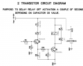
The purpose is to delay relay (k1.1) action, a couple of seconds after base of transistor Q2 is energized depending on capacitor C6.
The circuit diagram is as attached.
It seems to work on breadboard. However,
Here are my questions:
1) Is it reliable with respect to life of components?
2) Is it needed to have a diode just before C6 connection?
3) You can also make comment on the value of base resistor (R13) of transistor Q1.
Your help will be highly appreciated.
Thanks, in advance.

Moderators note : removed unnessesary white space
The circuit diagram is as attached.
It seems to work on breadboard. However,
Here are my questions:
1) Is it reliable with respect to life of components?
2) Is it needed to have a diode just before C6 connection?
3) You can also make comment on the value of base resistor (R13) of transistor Q1.
Your help will be highly appreciated.
Thanks, in advance.
Moderators note : removed unnessesary white space
Last edited by a moderator:

")


