Facebook
 Google
 GitHub
 Linkedin
I'm making this project https://www.arduinoslovakia.eu/blog/2019/1/attiny85---teplomer-s-ds18b20?lang=en
On display it is supposed to show the temperature value but the only thing I'm getting is "err" error, which the guy who wrote this code says this message will only pop up if uC finds no sensor (ds18b20).
The sensor I'm using is new and working. I have checked it with a code which displays temp on serial monitor of Arduino.
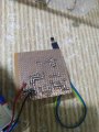
Here is what i have made look like, connections are all according to the schematic provided. Also why gnd and vdd both are connected to ground?
On display it is supposed to show the temperature value but the only thing I'm getting is "err" error, which the guy who wrote this code says this message will only pop up if uC finds no sensor (ds18b20).
The sensor I'm using is new and working. I have checked it with a code which displays temp on serial monitor of Arduino.
Here is what i have made look like, connections are all according to the schematic provided.
Also why gnd and vdd both are connected to ground?")