
Testing PCB with Digital IO

Thread Starter

fastbike

Joined Dec 29, 2020
128
I need some feedback on my ideas for semi automatic testing of a small number of PCBs I'm assembling.

The DUT is a PCB with an ATSAMD21 microcontroller. I've brought 16 digital IOs out onto an external header strip.
This board has a bootloader and connections to enable various firmware to be uploaded.

I'm thinking of writing a test program that I can upload that will exercise each IO, first as an input and then as an output.

I will use an Arduino or similar to interface with the IOs (from the DUT) via an array of pogo pins.

Now to my question: I would imagine a series resistor is need between the IO of DUT and the Arduino (say 150 ohm). Should I also have a pull down of around 5k ?

Any other ideas would be useful. Thanks
 
Last edited:
Thread Starter

fastbike

Joined Dec 29, 2020
128
Both the DUT and the Arduino (MKR) use ATSAMD21 microcontrollers. The IO pins can be configured for either pullup or pulldown when set as an input. These are nominally 40k (actual is between 20k and 60k) according to section 37.9.1 of the datasheet.

To test the output of the DUT pin, I would set the connected Arduino pin as an input with the internal pulldown enabled.
This would allow me to test the output of the DUT: if it is OFF then the Arduino will be pulled down by the internal resistor so a logic Low is detected. If the DUT output is ON the internal pull down on the Arduino will be insufficient to hold the input low so a logic High should be detected.

To test the input of the DUT pin, I would set the internal pull down of the DUT IO pin. Then when the Arduino output is OFF, the pulldown should ensure a logic Low is detected at the DUT. When the Arduino output is ON, the internal pull down on the DUT will be insufficient to hold the input low, so a logic High will be registered at the DUT.

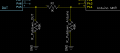
I think the series resistor can be a bit higher as the pull down resistors are quite high. A virtual schematic is attachedCapture1.PNG
 

MrChips

Joined Oct 2, 2009
34,758
In my opinion, I think testing an MCU loaded PCB is not very effective.
Instead, I would incorporate POST (power on self test) code in the app code itself.
 

Thread Starter

fastbike

Joined Dec 29, 2020
128
I'm settling on using an I2C multichannel general purpose IO chip such as the MCP23017. This will be connected via the I2C bus of the testing host, and via a 1k series resistors to the DUT IO port.
This will allow me to programmatically configure each of the IO pins on the DUT to be either an input or output. The corresponding channel on the MCP23017 will be configured as an output or input (with an internal weak pull up).
The testing software will send a signal to the DUT to either output a signal, or listen for a signal from the testing host.
Given that the DUT is network enabled via CAN it can report the results back to the host where the testing program will validate that the value is within spec.
 
Top





