test board for treadmill DCMDX ..#2

Thread Starter

Audiotrack

Joined Jan 6, 2022
20
Hi,

New here, first post. An older thread, but it is right on tune with something I am looking at right now...

G'day luca120.
The photo you attached was the final clue in the puzzle for me, and I successfully created a test jig for my DCMD57. If you or anyone else is interested in the answer, just let me know and I'll post the result.
Gary
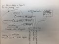
If ozwolf is able to post some more info about your test jig for this board it would be appreciated. It may greatly simplify a project I am working on. (Attempting to use the DCMD67 to drive a treadmill motor, hoping to use the rpm feedback loop to advantage if that works without the control panel as well)

Thanks.
 

Thread Starter

Audiotrack

Joined Jan 6, 2022
20
There are glimpses of a simple test rig in this video...
But not really enough to decipher. The language is in Portuguese I think. I may be able to get hold of the control panel for this board, will find out more tomorrow. Currently I only have the motor and the control/driver board. I am attempting to set up a PWM controlled treadmill motor for my lathe. I can do the PWM easily enough but I don't want to fiddle about with closed loop feedback since I think it will be more work than it sounds like. It would be far easier to use the original control/driver board if we can figure out how to drive it without the control panel.
 

Thread Starter

Audiotrack

Joined Jan 6, 2022
20
For context... I originally posted a question (post #1 here) on an existing thread, asking ozwolf (Gary) about a test setup he had created to drive the Endex DCMDX67, and was hoping he would see the request and share the schematic, since he had said he could make it available in the original thread that this one started from.

I'm currently looking at options. Will share any info I find.
 

Thread Starter

Audiotrack

Joined Jan 6, 2022
20
Quite a descriptive video of a similar board, worth the watch.

Have also been comparing photos of aftermarket direct replacements (so they say) from places like aliexpress, there are a few variations, the pinouts are marked on the boards, the abbreviations are a bit cryptic, but may be able to figure it out from there. Not sure which is correct and which is not so will post images once more confident that it is good info.
 

Thread Starter

Audiotrack

Joined Jan 6, 2022
20
DCMD67replacementpinout.png

This pinout of the 7 pin connector is from a photo of a replacement/clone DCMD67 board from an online seller. (not the original board that I have) I think if my board is in working condition it should be enough info to get at least an output from the motor terminals. So far I have traced the pin marked "CGQ" to go straight to the hall effect switch in the adjacent 2pin connector so I will assume that this "CGQ" pin sends the speed to the display panel for the operator to read the current speed. I am hoping that the closed loop speed control/feedback function happens internally on the main control board so that I can load up the treadmill motor and maintain constant speed. The pin marked "GD" I * think... might be the PWM input from the display board, but not certain. It is marked as 5V1 on a similar aftermarket replacement board but that makes no sense... I could not find any 5V pins on this connector at all. The "ST" pin would be the "stop" pin I am guessing. I can't remember if I made it active high or low but I could hear the relays clicking when I gave it a valid input. The "ST, S- and S+" pins all go to opto coupler inputs. I need to look further into this. The other side of the three optocouplers were commoned together... I didn't figure out where the common went to but maybe it is the three cathodes to ground, I just can't remember right now. It was a rushed look at work lunchtime and so a bit blurry at this point. Will hopefully have time to take another look in the next few days.

One weird thing is that I was getting a reading of 270VDC on the output of the bridge rectifier on my fluke meter (240v AC mains) My calculations for this would be a tad below 170VDC for an AC input of 240V so I wonder what is happening there. Or maybe there is a faulty diode and some AC leakage, not sure as I didn't have time to look into it any further. Or maybe my theory is so rusty that I made a mis-calculation.

I assume that the 5 pin connector is something to do with operator sensors...? hand grips/pulse rate or something? Or maybe incline up/down?

If someone with experience on similar boards could comment and at least let me know if I'm on the right track that would be appreciated.

Cheers.
 

Thread Starter

Audiotrack

Joined Jan 6, 2022
20
Hmmm... following from my last post I wonder if the DCMD67 uses serial comms to talk to the control panel or if the PWM is generated in the control panel and sent to the control board as I had assumed... ?
 

Thread Starter

Audiotrack

Joined Jan 6, 2022
20
Did some more testing, found the opto isolator for the stop/safety lock function had died and this function had become unresponsive. Likely I accidentally broke it somehow. For testing I bypassed the phototransistor output pins with a 240 ohm resistor which did the trick. I haven’t tested it properly but with a multimeter on the DC range on the motor output pins, it looks like activating the S+ pin makes the output to motor go 100% ( perhaps because the speed sensor was not detecting anything) and the S- pin was making it 0v output. Needs to be confirmed with a proper set up either the motor or check the output with an oscilloscope. This is only rough tests so far. Still unsure how to get proportional speed control or if the board will respond to an external PWM.
 

Thread Starter

Audiotrack

Joined Jan 6, 2022
20
Unsure if anyone is reading this or if there is any interest but I managed to get the Endex DCMD67 running as a speed control board without the control panel connected. It really is a simple exercise, I did do a minor hack to simplify the work to be done but the proper way should also be easy. Should I elaborate?
 

MaxHeadRoom

Joined Jul 18, 2013
28,617
Unsure if anyone is reading this or if there is any interest but I managed to get the Endex DCMD67 running as a speed control board without the control panel connected. It really is a simple exercise, I did do a minor hack to simplify the work to be done but the proper way should also be easy. Should I elaborate?
I would like to hear it! ;)
 

Thread Starter

Audiotrack

Joined Jan 6, 2022
20
Here is a rough sketch... For some reason I can’t find ground reference for the input side of the opto couplers, also the common to the anodes is -3.3V (correct for 15mA with 220R onboard resistors) and why -V (referenced from a nearby LDO but it’s not generating the -V) I’m confused at this stage. But managed to get the output working by wiring into the detector side of the opto’s.
 

Attachments

Thread Starter

Audiotrack

Joined Jan 6, 2022
20
In case it’s confusing, the 220R resistors and opto isolators and the SMPS style transformer in my sketch are all part of the board. The push buttons and the 240R resistors are a lash up to get an output to the motor.
 

Thread Starter

Audiotrack

Joined Jan 6, 2022
20
Have instead been concentrating on design of my own speed controller, but glancing back across this I’m thinking the negative offset discovered in part of the circuit may have something to do with getting sufficient drive voltage for the gate... Would need to reverse engineer the schematic to know for sure though.
 

Joe_D

Joined May 12, 2022
1
Hi Audiotrack, Great post. I'm trying to repair a DCMD67 board, I have a question regarding the Voltage across the Main Motor terminals (M+ M-). I'm measuring 240VDC. Also I was expecting to see a DC Pulse wave with a changing Duty cycle based on the Duty cycle from the optocoupler (U9-3020- Mofset Driver) PWM (i used a cheapy oscilloscope). However I'm seeing a straight 240V DC signal to M+/M-. I thought I had repaired the board with a new Mofset and U9-3020 optocoupler, however when I connected the motor and sent input signal for relay to open/close and the +speed simulation, I blew both the U9-3020 Optocoupler/Mofset/and Resistor R65/R64. Obviously I've got something wrong!!!.......Can you test your M+/M- DC output with an oscilloscope/or multi-meter and the 3020 optocoupler pin 2/3 (input) and Pin 5/6/7 (output). Your help is much appreciated. Regards Joe
 

markwtt

Joined Apr 27, 2023
1
Was struggling a bit with exactly how to get Endex DCMD67 style board working - then I came across this video which filled in all the pieces - even with the language barrier it is pretty easy to follow as he draws a circuit diagram as he goes, explaining exactly what is going on - the part I did not expect was that the +5v supply for the optocouplers comes from the external control board (makes sense when you think about it!) then once you have that connected the respective "stop" "speed up" "slow down" inputs are pulled to ground to activate what you need, dead easy once you know how :)
 

tedbar

Joined Nov 1, 2023
3
I have a DCMD67M board. It has been damaged with three components clearly fried - a TVS, R19 and R53. The TVS markings are still legible, however, the resistors not so. Is anyone able to tell me what values R19 and R53 are?
 
Top