@MrAl exactly i want to reduce the sensitivity to temperature
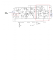
Dimensional changes in the electrode geometry due to temperature will add to the temperature dependence but the predominant contribution is from the temperature coefficient of the interelectrode capacitance of the oscillator transistor . Below an example using a temperature dependent current generator IT is mounted adjacent to the oscillator transistor T1 and drives a voltage controlled capacitor that forms part of Cb. the effectiveness of the temperature compensation depends upon the value of the sensor capacitance C.i want to use a temperature sensor similar to AD590 but the problem is that AD590 work with min +5 v and my circuit supply is 3.3 v
It has long been recognised that dielectric constant is a sensitive measure of the moisture content of soil. One method of measuring the dielectric constant of soil in the field is to incorporate the soil as part of the dielectric of a capacitor..with the sensor inserted in the access tube, measures the capacitance of the electrode system with dielectric comprising the in-situ moist soil surrounding the access tube. The capacitor forms part of the feedback loop of a modified Clapp high-frequency transistor oscillator operating at about 150 MHz. This type of oscillator is particularly stable and suitable for high-frequency operation.The relation between the measuring capacitance and the dielectric constant C= g Er
by measurement of the capacitance we can calculate dielectric constant of soil Er anf then determine soil moisture by empirical relation etwen the permittivity and soil water contain
below soil moisture sensor develloped by Dean 1987 and 1994 which use a modified clapp oscillator operating around 150 MHZ and use a temperature compensation system to reduce the sensittivity to temperature ( IH 125 show page 11 )
(Moderator's note: A copyright protected report has been removed. Below is a link to that document.) nora.nerc.ac.uk/7368/1/IH_125.pdf
I hate to say it but there are a lot of approaches to this. MrChips mentioned one and i'll mention a few other ways.
The first is probably the oldest. That's using a thermistpr. The thermistor is put in contact with the sample, it changes resistance with temperature of the sample. What you do with that information can come in at least two forms: one where you measure the resistance, calculate the temperature, and use empirical data to compensate. This can be calibrated pretty well. The second is where you find a place in your circuit that changes your required parameter with a change in resistance at that point, then use a thermistor possibly with series and parallel fixed resistors to change the slope. This gives partial compensation and is probably the oldest way of doing it as it is purely analog and uses only passive elements to trim the sensor. The drawback to this second way is that you have to choose the thermistor value and external resistors very carefully and if you dont have a functional form for your circuit then you have to do this by trial and error which is very time consuming.
The second is to use two different components, one with positive temperature coefficient and one with negative temperature coefficient. For example, two capacitors in series with opposite temp co's will maintain relatively constant capacitance, but the drawback is the two have to be hand selected and tested. This will only work if you can create or find the two required components.
The third is to measure the temperature as you seem to want to do, then compensate using empirical data. If you cant find a temperature sensor that works at 3.3v then keep looking. This method is probably best when you can use a microcontroller or computer host.
Another method is to use a string of Si diodes and use their change in voltage with temperature to measure and thus compensate for the sensor change.
Still yet another method is to take a physical sample, then hold it at a constant temperature, and have the empirical data on hand for that particular temperature. This is a very reliable method but you have to take the time to heat the sample up to the required temperature, which has to always be above any ambient.
I dont know how many samples you have to take at any one time, but if you could bring them back to the lab with you another method might be to boil the moisture out of the sample and condense it back into liquid, then measure the amount of liquid vs the amount of soil left over. This is more time consuming of course but may be a good way to do it if the number of samples is not too large. Could probably build a field version too, but it will take more time to get a reading of course. Small percentages will be harder to read.
i found this in internet speaking about positive temperature coefficient and one with negative temp coef . how can i do that without changing the oscillator frequency output ( around 150 MHz ) ??
(Moderator's note: A copyright protected book chapter has been removed. Below is a link to that document. The referenced content is chapter 10.) www.qrparci.org/wa0itp/csts_book.pdf
Well actually in your app isnt the probe the capacitor? IF that's the case, you'd have to figure out how to build a probe with the opposite temperature profile.
This may not be possible, but i dont rule out anything when it comes to human invention.
what about temp sensor , because i will read the frequency output with arduino that's why i make my oscillator power supply 3.3 v which work with arduino !!
Whilst the Clapp oscillator is substantially insensitive to temperature there is a residual dependence and other factors,such as thermal expansion of the rods and their spacing, contribute to a resultant temperature coefficient which the inherent oscillator stability, of 1 in 10^4 makes clearly visible. To reduce its significance temperature compensating circuit is included comprising a temperature sensor, the AD590, an amplifier and two variable capacitance diodes, BB809s. The resultant stability is 1 in 10^4 per degree C. For the middle of the range this is about equivalent to .02 per cent water content per degree C.
If you are reading the temperature with a sensor and get that data, then cant you just compensate with that info in code? Or do you have to keep the frequency very stable too?
If you do have to keep the frequency stable too, can you go with a different oscillator or not?
How are you going to measure 150MHz on an Arduino?
Here is how I would measure soil moisture content:
Two MCU GPIO pins are configured, alternating between output and input in order to charge/discharge the RC circuit. This in essence creates a bipolar oscillating circuit using the probe as part of the RC circuit.
The MCU can easily measure the oscillator frequency.
Select R1 and C1 values to suit your application, i.e. you can measure soil capacitance or conductivity.
You can add voltage variable capacitor diodes to your oscillator so that it becomes a voltage controlled oscillator, but with a small range. Drive the VCO control voltage with well filtered PMW from your Arduino -you may need to use a 16 bit PWM channel.
Take the temperature information from a DS18B20 (3 volt - 5 volt power supply) sensor into your Arduino.Create a look-up table (temperature in, PWM value out) that compensates for thermal drift.
By the way, have you considered running your Arduino from +5 volts so you have a wider range of sensors available?
but i' using arduino to read the frequency output of my oscillator , not for temperature compensation !!
the frequency of my oscillator will be variable with soil moisture ( by electrodes ) , how can i change my oscillator to VCO with variable capacitance of the electrodes ?
(Some text removed for clarity)To reduce its significance temperature compensating circuit is included comprising a temperature sensor, the AD590, an amplifier and two variable capacitance diodes, BB809s. The resultant stability is 1 in 10^4 per degree C. For the middle of the range this is about equivalent to .02 per cent water content per degree C.
You seemed to have outlined a good solution above. If the only thing holding you back is the AD590's requirement for a 4 volt power supply, you can run your Arduino at 5 volts or use level shifting circuitry between your Arduino and the temperature sensor.
but i' using arduino to read the frequency output of my oscillator , not for temperature compensation !! the frequency of my oscillator will be variable with soil moisture ( by electrodes ) , how can i change my oscillator to VCO with variable capacitance of the electrodes ?
You posted a schematic in Post #29 clapp oscillator with compensation What specifically is it that you need that this circuit does not do for you?
Just in case this is useful to you:
If you want the oscillator to be self-temperature compensated you can replace one or more of the capacitors in the tank circuit with an NPO capacitor in a series or parallel combination with a smaller capacitor (for example a large COG in parallel with a small P100) so teh total change in capacitance with temperature compensates for the drift of the rest of the oscillator. I think this is explained on pages 3 and 4 of Chapter 10 of Crystal Sets to Sideband, which you posted in post #26.
my oscillator will be within an access tube , which will be injected in soil , so using trimmer capacitor is not the good choice ! but the idea of self compensated oscillator sound good ..
hello , i found on net an invention ( temperature compensation circuit for oscillator with parabolic characteristic ) 1985 , this invention is what i want for my soil moisture sensor , but it's seems difficult and need many circuits , there isn't an integrated circuit which have the same fonction today ?
The patent went to Motorola which is the predecessor of On Semi. Looking through ON Semi offerings, I did not spot anything that looks like it might be this in IC form.
This is to improve the frequency stability of an oscillator whose change with respect to temperature is parabolic. Your oscillator would probably not be parabolic until it is frequency compensated.
 Facebook
 Google
 GitHub
 Linkedin