Synchronous Rectification Simulation help

Thread Starter

jlawley1969

Joined Feb 22, 2021
97
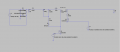
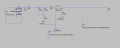
Hi So I am having an issue with the simulation of an Synchronous Rectification just as a proof of concept. The issue isnt getting it to work the issue is that even if I dont have a voltage applied to the gate of the MOSFET it rectifies just the same which is weird. I have tried many different MOSFETs(all with plenty breakdown voltage margin) in the simulation and most follow this trend but some do in fact show a non rectified voltage with no gate voltage. I Just want to know if this is a problem with the simulation or that the different MOSFETs actually perform this way in the real world.
I have attached images with "SyncControl" being the ...control as in no MOSFET whatsoever and the rest should be self explanitory
 

Attachments

crutschow

Joined Mar 14, 2008
34,285
if I dont have a voltage applied to the gate of the MOSFET it rectifies just the same which is weird.
Not weird at all.

All MOSFETs have a source-drain substrate diodes which is reverse-biased with normal transistor bias, but will act as a rectifier for the opposite polarity of the MOSFET, independent of the gate-source voltage (symbol below shows this).
Turning on the MOSFET when biased in the reverse direction just reduces the drain-source voltage from one diode-drop to whatever its on-resistance will generate (a MOSFET conducts equally well in either direction when ON).

1636382398115.png
 
Last edited:

Thread Starter

jlawley1969

Joined Feb 22, 2021
97
Not weird at all.

All MOSFETs have a source-drain substrate diodes which is reverse-biased with normal transistor bias, but will act as a rectifier for the opposite polarity of the MOSFET, independent of the gate-source voltage (symbol below shows this).
Turning on the MOSFET when biased in the reverse direction just reduces the drain-source voltage from one diode-drop to whatever its on-resistance will generate (a MOSFET conducts equally well in either direction when ON).

View attachment 252160
so turning on the MOSFET essentially just improves efficiency? so it doesnt have to be conducted through the body diode?
 

crutschow

Joined Mar 14, 2008
34,285
so turning on the MOSFET essentially just improves efficiency? so it doesnt have to be conducted through the body diode?
Yes.
That's why a synchronous rectifier is used in place of a diode.

Below is an LTspice simulation showing this:
During the first half of the positive input, the P-MOSFET is off (red trace), showing the diode drop from the body diode in the output (yellow trace) as compared to the input (green trace).
When the MOSFET is turned on at the positive peak, the diode drop disappears, as the current is now being carried by the MOSFET channel and the drop is now determined by the MOSFET's low on-resistance.

The purple trace shows the MOSFET power dissipation.
Note how it drops to very near zero when the MOSFET is turned on.

1636397906006.png
 
Last edited:
Top