Symmetry in Wien-bridge

Thread Starter

magician87

Joined Apr 12, 2009
2
I was doing an experiment about sine wave generator. And I bumped into some conflict between the experimental result and what is explained in my text, Microelectronic Circuit of Sedra & Smith.

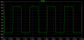
What is said in the text book is that the R4=R5 and R3=R6 will guarantee a symmetric sine wave. But in my experiment, that is not the only case. When I used different values for R4 and R5, still I got a symmetric wave, and the wave form seems to be determined only by the smaller resistor. Even when I took R4 out of the circuit (i.e, replace R4 by infinity) I still got a symmetric sine wave.
Could some one help me explain this?
Thx a lot
 
The circuit appears to be an inverting amplifier configured to operate as an oscillator whose oscillation frequency is determined by Rs, Cs, Rp, and Cp, the gain is determined by R1 and R2.................the peak positive amplitude and negative amplitude of the output wave would be determined by the resistor/diode feedback network. The wave should always be a 'sine' wave, but the resistors R2,R3,R4,R5, and diodes D1,D2 make sure that the ouputted wave has a 'zero' at 0 or ground.....or so I would presume.

I've had op-amp circuits where the zero of the sine wave was offset from actual ground and I would have to fine tune the power supplies in order to get it properly referenced to ground. This circuit appears to keep the system some what referenced in the case of the supplies rails not being symetrical.

Anyways have fun!
 

Ron H

Joined Apr 14, 2005
7,063
When I simulate the circuit with one of the diodes omitted, the output is not symmetrical, but the difference is subtle.
 

Thread Starter

magician87

Joined Apr 12, 2009
2
thanks guys. I didn't think of the case that the offset is not 0V as I assumed I set the scope's coupling to be AC. Anyway, the fact that the output must be sine wave still bothers me. I feel really uncomfortable with the explanation that because of the sustained oscillation, the output must be a sine.
 

Ron H

Joined Apr 14, 2005
7,063
thanks guys. I didn't think of the case that the offset is not 0V as I assumed I set the scope's coupling to be AC. Anyway, the fact that the output must be sine wave still bothers me. I feel really uncomfortable with the explanation that because of the sustained oscillation, the output must be a sine.
The amplifier and feedback must be absolutely linear for the output to be a pure sine wave with no distortion (harmonics). Assuming linearity, the output is a sine wave because there is only one frequency where the phase shift around the loop is exactly 360°.

If the amplifier is not linear, the output can have a lot of distortion. Below is the simulated output waveform of a TL071 Wien bridge oscillator with the closed loop gain set at 11 instead of 3 (exactly 3 is required for a sine wave).
 

Attachments

Wendy

Joined Mar 24, 2008
23,798
If this is off topic let me know, but I'm trying to understand the gain control on this circuit. The old HP solution is very intuitive, this one isn't.

Of course if the waveform isn't a pure sinewave it would be a lot more understandable. The gain toward the top of the sine wave is actually reduced somewhat, due to the breakover and conduction of the diodes.
 

Ron H

Joined Apr 14, 2005
7,063
If this is off topic let me know, but I'm trying to understand the gain control on this circuit. The old HP solution is very intuitive, this one isn't.

Of course if the waveform isn't a pure sinewave it would be a lot more understandable. The gain toward the top of the sine wave is actually reduced somewhat, due to the breakover and conduction of the diodes.
You're right. It's going to add (only) odd harmonic distortion, due to the reduced gain at the peaks, if the circuit is perfectly symmetrical.
 
Top