Switching losses in ULN2003 driver

Thread Starter

prodigyaj

Joined Dec 11, 2007
48
thanks for the replies ! its a little too much of an ask , my pcb is kind of ready would there be any pin to pin compatible mosfet ics which is replacable with ULN2003 ? otherwise I will have to make the entire pcb again which of course I would if no option left
 

eblc1388

Joined Nov 28, 2008
1,542
thanks for the replies ! its a little too much of an ask , my pcb is kind of ready would there be any pin to pin compatible mosfet ics which is replacable with ULN2003 ? otherwise I will have to make the entire pcb again which of course I would if no option left
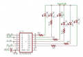
Try this if you don't want to re-design your PCB.

You can try the circuit out somewhere or ask someone to do it before you finalize your PCB design. Its just a few minutes work using a frequency generator and an oscilloscope. The result is definite.


Attachments

Ron H

Joined Apr 14, 2005
7,063
As Ron_H mentioned, you'd be better off with a logic-level MOSFET. I was in the process of looking for a decent candidate; you might consider looking at a TN0604, which has four N-channel MOSFETs in a single 20-pin SOW package. Mouser has a TO-92 single-channel version which will be easier for a hobbyist to deal with:
http://mouser.com/Search/ProductDetail.aspx?R=TN0604N3-Gvirtualkey68900000virtualkey689-TN0604N3-G

The threshold voltage is only 1.6v, which is quite low.
I personally wouldn't buy it for this application if it was a production design (which it almost certainly isn't), because Rds(on) is not spec'ed below Vgs=5V. It would probably work OK in a one-off application.
 

Audioguru

Joined Dec 20, 2007
11,248
Also SFH4503 takes 1.5V and not 1.8V as suggested ( 1.8V is when u keep it on for 20ms and the junction temperature increases and thus increases the junction voltage, here i plan not more than 20uS ) So again the question comes back to voltage drop across ULN2003 at 50Khz to 100Khz :)
The forward voltage of LEDs is a range of voltages. This one is typically 1.5V but can be as high as 1.8V. If you don't believe it then measure yours.
 

Ron H

Joined Apr 14, 2005
7,063
Also SFH4503 takes 1.5V and not 1.8V as suggested ( 1.8V is when u keep it on for 20ms and the junction temperature increases and thus increases the junction voltage,
That's wrong. The datasheet says the temperature coefficient of Vf at If=100mA is -1.5mV/°K. The forward voltage goes down as the temperature goes up, just as in any other semiconductor diode.
 

Thread Starter

prodigyaj

Joined Dec 11, 2007
48
Hello all !!
I cut the tracks of my pcb and changed as L.Chung suggested. Although I used little different values.

I checked my uln2003 losses and it gave me consisten 0.57v loss per channel. So assume it to be 0.6 that leaves me with 2.7V. Of which according to the datasheet graph 1.8V forward voltage drop brings atleast 100mA current.

2.7-1.8=0.9 and 0.9 / 0.1 = 9Ohms. So the resistance i selected is 9Ohms !! I hope that fits in well and used every resistor as 9ohms.

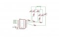
schematic.JPG

heres the diagram of my circuit and each with 9ohm resistance. Also please not each channel is activated only one at a time.

I first put on the FR_IR and FL_IR pulsed them at 15uS and got excellent response. Simalarly for SR_IR and SL_IR and also for DR_IR and DL_IR. The pairs where intitally tested individually and they worked beautifully. Now the inputs to the uln are connected to the microcontroller, and in our application we require each pair to be activated. So when a code for such a type was written apparantly only 2pairs worked out of 3pairs !! Infact the pair which dint work had a drop accross the IR led equal to the drop of IR led of other working pairs but through the cam you cldnt see them glow. Then we again tested for individual pairs and this time onwards the FL_IR and DR_IR+DL_IR fails to work (although there is still the same amount of diode drop as across other working ones and every hardware aspect is checked out ). I know this got a little long but then I thought of a comprehensive put forward of my problem and observations. The remaining FR_IR and SR_IR+SL_IR continue to work as brilliantly as they can ever be !!
 
Last edited:

Ron H

Joined Apr 14, 2005
7,063
I checked my uln2003 losses and it gave me consisten 0.57v loss per channel. So assume it to be 0.6 that leaves me with 2.7V.
Did you check this with 100mA and 200mA load? The TI datasheet (Fig. 11) shows that you should expect Vce(sat) of about 0.8V for 100mA and 1V for 200mA.
EDIT: You can parallel inputs instead of LEDs, using one output per LED. This will give you the same Vce(sat) for each output.
 

Thread Starter

prodigyaj

Joined Dec 11, 2007
48
Yeah i did check the datasheets but drew 2 conclusions from it :
1 - Min value is not specified so chances are my uln is going to a min value
2 - Even if its 0.9V it did work when i tested the module individually !!! I am not to worried about the current if for 50mA also i get a good radiant intensity ( which i did when testing only pairs ) i guess that serves my purpose. Putting higher resistance would only lower the current and not burn my components and i can easily change my resistance if i find the need to do so
 

eblc1388

Joined Nov 28, 2008
1,542
I first put on the FR_IR and FL_IR pulsed them at 15uS and got excellent response. Simalarly for SR_IR and SL_IR and also for DR_IR and DL_IR. The pairs where intitally tested individually and they worked beautifully. Now the inputs to the uln are connected to the microcontroller, and in our application we require each pair to be activated. So when a code for such a type was written apparantly only 2pairs worked out of 3pairs !!
For the IR diode which did not work, I think you have killed it by passing high current through it.

How you have actually did that I do not know. Maybe coding problem. Half a second at 100mA will surely kill them.
 

Thread Starter

prodigyaj

Joined Dec 11, 2007
48
Sir, when a diode gets killed dont you think the voltage across the diode should be open or anything that is not consistent with the other working diodes ?
Surprisingly I am getting exactly the same voltage across the 'killed' diodes as across the ones that are working.
As far as I know I am confident not to keep them on for more than 15uS.
Pleasse give in your suggestions of the possible problems as you all have been doing so far !
Thank you

Regards

AJ
 

SgtWookie

Joined Jul 17, 2007
22,230
Start out with low current, and progress to higher currents.

You started out with high currents, and have thus killed those diodes that couldn't handle the current.

A very common affliction among diodes that have been subjected to excess current is that they become very dim.

Replace the diodes that are burned with new ones, and the resistors with values significantly higher.
 

Thread Starter

prodigyaj

Joined Dec 11, 2007
48
Yeah I will surely do that. I think I am convinced that the diodes have been killed. But what voltages do you find across the diode when it gets damaged ?
 

SgtWookie

Joined Jul 17, 2007
22,230
Yeah I will surely do that. I think I am convinced that the diodes have been killed. But what voltages do you find across the diode when it gets damaged ?
I don't know; they're your diodes. :confused:

The diode manufacturer gives a range of specifications for Vf @ a particular current; minimum, typical and maximum. Those LEDs you've already burned out were the most desireable; those with the lowest Vf.

You can't specify Vf @ current when purchasing LEDs, as everyone wants the lowest Vf possible.

Since 3/5 of your LEDs are already fried, I suggest that your other two LEDs may also be close to dying - but don't take them out just yet.

Your system has an extremely low tolerance to voltage fluctuations. Even a minor "glitch" (transient) will kill your LEDs.

Since you're powering your LEDs from 3.3v, your best bet is to place them in parallel. This means that the current limiting resistors will bear the brunt of fluctuations in current due to voltage fluctuations.

If this is not acceptable to you, then you must improve your voltage regulation significantly.

Also, you must "size" your LEDs by individually determining their Vf at their rated current. If you don't do this when you are operating at close margins, you will fry quite a few LEDs. The alternative choice is to accept dim LEDs, and produce an inferior product.
 

Thread Starter

prodigyaj

Joined Dec 11, 2007
48
Before I replaced my LED's I decided to test it for the very last time. Just connected the multimeter in the continuity mode and surprisingly all the leds glowed infornt of the camera!! But dosent glow under code control when hihger currents are made to pass through it !
 

Thread Starter

prodigyaj

Joined Dec 11, 2007
48
Hello all, I guess all my problems are solved thanks to all of you and patiently replying to some of my obvious doubts. Specailly would like to thank Lu Chang !! At my end everything is working fine now.
I would like to summarize what I did for the benefit of others if at all they encounter the problem :

The uln drop had to be sorted by removing the IR led from series and putting it in parallel.
(Please dont hit me for this error :) ) There was small solder material that shorted my input pins of the microcontroller and hence the following problem.
 

Ron H

Joined Apr 14, 2005
7,063
You will get better current matching, and slightly more brightness, if you do it like this, as I and others have suggested. If you need the two additional ULN2003 outputs for something else, then your method is OK.
 

Attachments

Top