 Facebook
 Google
 GitHub
 Linkedin
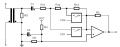
The circuit attached is from this App Note.
In my case I need just two gains: unity and 60, so I need only a switch.
In the app note they say:
My second question is about coupling capacitor C1. How do I calculate the level of attenuation caused by the high pass filter formed by C1 and R11, R12, R13?
In my case I need just two gains: unity and 60, so I need only a switch.
In the app note they say:
So in my case with two gains (1 & 60) the difference is more than the recommended. But what's the reason behind this? How is the accuracy affected?Gain adjustment resistors are dimensioned such that each range has an amplification of about eight times the previous.
The number of switches may well be increased and the gain difference decreased, however, it is not recommended to
have a larger gain difference than eight between two subsequent ranges. This because gain differences of around ten,
and higher, cause the signal to degrade below 1% accuracy before it can be further amplified.
My second question is about coupling capacitor C1. How do I calculate the level of attenuation caused by the high pass filter formed by C1 and R11, R12, R13?
Attachments
-
 20.9 KB Views: 18


