Facebook
 Google
 GitHub
 Linkedin
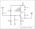
I'm freshman . I don't know what is exactly going on here but I made this fm transmitter.
Could anyone please explain to me the different stages of this circuit ? Like, what is required by a transmitter, and where it is in the circuit... This will help me and understand the circuit a bit better..
http://makezine.com/projects/super-simple-fm-transmitter/
Thanks
Could anyone please explain to me the different stages of this circuit ? Like, what is required by a transmitter, and where it is in the circuit... This will help me and understand the circuit a bit better..
http://makezine.com/projects/super-simple-fm-transmitter/
Thanks
Attachments
-
 17.1 KB Views: 695