Super cool signal device

Thread Starter

gravitor91

Joined Jul 22, 2013
4
Hey guys im a newbie and need a solution to a problem i've encountered. Here it is... There is a point in the circuit where the resistence has to vary between 9 given points at a given frequency (from 1Hz to about 40Hz or even less). IDK how to make it happen in a clean way, my initial idea was a rotating engine and a set of pots but thats no good, im thinking microcontroller switch or something but im clueless about that... any help ? :)

BTW the device is 9v low amp circuit so there isn't much power involved
 

wayneh

Joined Sep 9, 2010
18,183
I have no clue what you're talking about. A schematic will save a lot of time. Maybe you just need a potentiometer? What does frequency have to do with adjusting resistance?
 

Thread Starter

gravitor91

Joined Jul 22, 2013
4
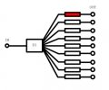
ok sorry for the confusing description wayneh, let me go at it again, im making a signal distorting device which depends upon the value of resistor between the IN and OUT, but that value must not be constant, but variate between the 9 other possible resistences conected at it, one at a time. So D1 would be a signal switch of some sort that automatically turns R1 on, and all others off, then proceeds to turning R2 on, and all others off, and so on. The frequency on which the D1 returns to R1 (red) is to be variable, and between 1Hz and 40Hz or so.
Here is an image of it.
 

Attachments

odinhg

Joined Jul 22, 2009
65
If you've got a microcontroller already, maybe you could use a digital potentiometer?

Or something less expensive like a 4017 counter controlling some FETs and clocked from a schmitt trigger oscillator?
 

wayneh

Joined Sep 9, 2010
18,183
Thanks for making it much clearer.

How much current needs to flow through each leg? I assume it's not much, less than 5mA perhaps.

I also think the 4017 counter might be a good approach. Depending on what you need, maybe the counter output could be used directly. If not, you could use the output to drive MOSFETs on and off. While "on", they would add only mΩ to your resistors. The counter will allow you to sequence up to 10 different "states" in any order. You won't be able to change the order without re-wiring, but maybe that's OK in your application. I'd use a 555 timer IC to generate the clock to advance the 4017 timer.
 

Thread Starter

gravitor91

Joined Jul 22, 2013
4
IDK how to set up the microcontroler, all i have is a Launchpad MSP4030, and im cheching out the 4017 counter and how it works, apparently this counter can do the switching between the exits, i can make the connections to pots to regulate, no need for the digital pot peraps, right ?
 

Thread Starter

gravitor91

Joined Jul 22, 2013
4
Nice, i have the 555 timer but i only used it to set a PWM, id have to put it before the 4017 for some specific reason then or the 4017 can do it all? BTW the current is low, id say around 5mA or so
 

odinhg

Joined Jul 22, 2009
65
Could you share with us how this fits into the rest of your circuit? Some more information on the complete circuit.

And yes, you could use a 555 to generate the clock for the 4017. The 4017 needs an external clock to function.
 
Top