SUCCESS STORIES: Repair thermoelectric cooler

MrChips

Joined Oct 2, 2009
35,271
The #1 suspect is C8, 47μF / 25V which is located beside a hot heat sink.
There is nothing to lose by replacing it in every situation. It is recommended that you go with a higher voltage, 35V or 63V if it fits the same footprint and lead spacing.
 

K6216

Joined Jul 23, 2017
21
The #1 suspect is C8, 47μF / 25V which is located beside a hot heat sink.
There is nothing to lose by replacing it in every situation. It is recommended that you go with a higher voltage, 35V or 63V if it fits the same footprint and lead spacing.
Yes, this is true because C8 is the primary filter capacitor for both the VCC supply to the TL494 regulator and the bias voltage for the control feedback transformer. When it looses its capacity and ESR increases, the entire control feedback system fails. But on this FX100-1 PCB every single electrolytic capacitor was either way under value or had 10X ESR of new capacitor (or both!) Your mileage may very...

Some of the 4.7uF caps are in snubber circuits. When these degrade the remaining spikes degrade or kill diodes & transistors. Other 4.7uF & 47uF caps stabilize regulators and control logic. When these fail things tend to ring or oscillate. If only the weakest failure point is repaired, I can assure you that the power supply will fail again in short order due to the second most likely failure point.

It is a lot of work to replace all the capacitors, but if the next failure takes out the primary BJT transistors due to control loop oscillations there is even more work to disassemble the refrigerator yet again and find the problem. The electrolytic capacitor brand used in these Hanyi Computer Device supplies are of very poor quality with an extremely short life. Any quality cap brand will make these supplies outlast the thermo-electric cooling unit. (Corollary to "measure twice cut once" is "repair once then enjoy cold wine".)
 

Squatch

Joined May 8, 2017
2
Going back to your original board, R41', standing vertically to the right of the smaller transformer, appears to have a burn mark at the bottom. Might be worth testing, if you can be bothered now!
I have just successfully repaired my thermoelectric cooling power supply board - 110V Input Refrigerator Fridge Control Board 6A160904 HYS80-12J PCB160603F2. It was in an Avanti mini-frig, 1.7cu/ft.

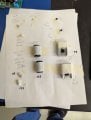
The component's layout numbers are correct on the sheet of paper in the picture.

The capacitor C12 probably caused the whole problem. It is listed on the schematic I downloaded from the “All about Circuits forum” web page, which shows it as C21. It looks as if it may have overheated and leaked out all its dielectric juices. This caused D16, and D17 to short and all hell broke loose then shorting out T6, T7 R35, and the two transformer-driving transistors T4 and T5. I just automatically decided to replace the 4.7uF caps/50vdc. As I was putting the unit together I noticed the green capacitor-looking part next to the fuse, RTC005/04. I replaced it with an Ametherm-ICL 17.5 OHM 25% 4A 11.5MM (p/n - SL12 17004).
I got my parts from Digikey:
2 X - MJE13005 PBFREE - TRANS NPN 400V 4A TO-220-3
2 X - EKXG201ELL221MM25S - CAP ALUM 220UF 20% 200V RADIAL
2 X - KSC1815YTA -TRANS NPN 50V 0.15A TO-92-3
2 X -1N5399 - DIODE STD 1000V 1.5A DO204AC
2 X -ECA-1HM4R7B - CAP ALUM 4.7UF 20% 50V RADIAL TH
Total = $14.58

I had the NTC on hand.
I plugged the unit up and the fans started running and then when I turned the power on it started cooling immediately. Works great!
 

Attachments

gsch

Joined Apr 4, 2021
2
About 4 years ago, one of the two FX-101 boards failed and would no longer turn the cooling on. I followed the advice here, and replaced almost all the capacitors on the board (I left the three largest ones alone). It has been working ever since. A while later, the second board failed in the same way. I was pressed for time, and only changed C8, as it was the one most people said usually caused the problem. That board started working, and continued working until a couple of weeks ago. Now it would not turn the cooling off. So I changed the other capacitors (except the three largest ones). It started working. I checked the capacitance of the old capacitors, and all but CA1 were close to their nominal values. It was only about 15 instead of 47 microfarads. I have no way of measuring ESR, so those values remain unknown.

Thanks to all who have contributed to all the great information and advice found in this thread.
 

MrChips

Joined Oct 2, 2009
35,271
This thread is intended for SUCCESS STORIES only.
If you post here for reasons other than a success story or asking for information on repairing your appliance it will be moved to its own thread,
 

Adogg96266

Joined Jun 20, 2025
1
New to the forums but SUCCESS with my Craigslist Wine Enthusiast
Dual zone so 2 boards and 2 TECs

C8 caps replaced on both boards, got fans spinning again and one side started cooling but soon failed.

Replaced with cheapo Amazon TECs (4 for 17 bucks) and artic silver thermal compound and got both sides cooling.

As is with cheapo components one TEC failed in a day so replaced again...enjoying nice cool reds and chilled whites!
 
Last edited:
I’ve worked on a few thermoelectric cooler repairs as well, and one of the key challenges is identifying whether the issue is with the TEC module itself or the power supply. In many cases, degraded solder joints or inadequate heat dissipation cause failures. Ensuring proper thermal management (heatsinks + thermal paste) makes a huge difference in long-term performance.


Has anyone here tried upgrading to higher-efficiency TEC modules when replacing failed ones? I’ve seen improved results with modern Peltier elements.
 

dudu8

Joined Oct 10, 2025
1
Hi there, I wanted to thank all on this forum for the valuable suggestions and advice provided!

My board is a Foshan Hanyi Computer board powering a 12V thermoelectric Farfalla wine cooler model FWC-40BK. This board does not fully resemble the FX-101 nor the FX-102 and I could not find a replacement board.

After reading the entries into this forum, I decided to take a stab at trying to fix it, because it somewhat looked similar on the PSB side. Through a few trial and errors (I am not electrically trained), multiple bad soldering joints (had to learn to repair a trace + pad I accidentally tore up), loads of youtube videos and a couple of electronics books, I finally fixed it. Success! Had to replace 6 caps (slightly different numbering so I won't include here), two D13007K power transistors, a 2 ohm resistor and all the 4 bridge rectifier diodes (IN4007). Plus the fuse a couple of times. Indeed C8 was really in bad shape with high ESR.

Special thanks to kcvogels for his above advice, as I had missed the bridge rectifier and the 2 ohm resistor. Every entry in this forum counts.


Hi there! 3 years later, facing the same situation as you - how has your repair lasted over the years? :)
 

hueypic

Joined Sep 12, 2017
10
Had a board (lower, TEC only) that went bad. It went for a while, I'd have to reset it (I put a wifi controlled plug on the power cord) but after a while, that didnt even work. I was too busy to pull it apart, so I ordered an FX board and it is going strong.
The C10 (2200uf) cap was slightly swollen, so I changed that out. Someone up thread said it was a reservoir I think.
When I installed the new board, noticed the upper board (also controls display) Red LED was slowly pulsing. I also had to coax it into starting by raising the temp setting up to its warmest immediately after plugging it in. After swapping the C10, I put that board in and while the LED isnt as bright as the new one, there is no pulsing and it is still starting great.
So now I have a spare board and a stock of 2200uf and 47uf (for C8) available.
BTW, the C10 I pulled out measured about 1500uf.
 

boggle

Joined Nov 22, 2025
1
Tried fixing my dual-zone fridge that's lost both zones over the years, seems to have two separate HYS60-12-KD. One had a visibly bulging C10 so I went ahead and replaced that along with both C8s. Upon reconnecting the fan on the TEC spun up for about 30 seconds before the board sounded like a gang of angry bees. Hooked up my bench supply to both TECs, pulling 4A at 12V and see to be generating a good bit of head so I might just replace the boards instead of continuing to play whack a mole.
 

frunch217

Joined Nov 13, 2025
1
Happy to add another success story to the thread! Thanks to the helpful souls here i wound up repairing one of these units for a customer recently. They had a wine refrigerator built into a nice cabinet/bar furnishing but the upper and lower units stopped working. It was a CD-110-C board i had pulled out for the upper TEC and replaced C8 and i believe it was CA1 or CA10 (both that i replaced were 47uf caps that were closer to the power side of the circuit)...I didn't have a means of measuring ESR on them, but reinstalling the board actually got *both* upper and lower units working a few days ago without a peep since.

I'm very excited to learn about these, this thread was very very helpful! I'll certainly be looking out for these in the future, as i get requests to fix wine refrigerators from time to time. I added a few pics from the board and the schematic from the back of the unit i was servicing.

Thanks for the help!!
 

MrChips

Joined Oct 2, 2009
35,271
Happy to add another success story to the thread! Thanks to the helpful souls here i wound up repairing one of these units for a customer recently. They had a wine refrigerator built into a nice cabinet/bar furnishing but the upper and lower units stopped working. It was a CD-110-C board i had pulled out for the upper TEC and replaced C8 and i believe it was CA1 or CA10 (both that i replaced were 47uf caps that were closer to the power side of the circuit)...I didn't have a means of measuring ESR on them, but reinstalling the board actually got *both* upper and lower units working a few days ago without a peep since.

I'm very excited to learn about these, this thread was very very helpful! I'll certainly be looking out for these in the future, as i get requests to fix wine refrigerators from time to time. I added a few pics from the board and the schematic from the back of the unit i was servicing.

Thanks for the help!!
That's great news and welcome to AAC!
Keep the success stories coming.
 

painist

Joined Dec 7, 2025
1
Happy to add another success story to the thread! Thanks to the helpful souls here i wound up repairing one of these units for a customer recently. They had a wine refrigerator built into a nice cabinet/bar furnishing but the upper and lower units stopped working. It was a CD-110-C board i had pulled out for the upper TEC and replaced C8 and i believe it was CA1 or CA10 (both that i replaced were 47uf caps that were closer to the power side of the circuit)...I didn't have a means of measuring ESR on them, but reinstalling the board actually got *both* upper and lower units working a few days ago without a peep since.

I'm very excited to learn about these, this thread was very very helpful! I'll certainly be looking out for these in the future, as i get requests to fix wine refrigerators from time to time. I added a few pics from the board and the schematic from the back of the unit i was servicing.

Thanks for the help!!
Frunch217
Thanks for the insight. My (8) Bottles Wine Cooler stopped working and I replace (all) the Electrolytic Capacitors, as there ESR were testing low. I also found one of the NPN transistor, and the Schottky diode were also bad and replaced then.
The unit lights up, LED lit, and I can adjust the temperature, but I get 'E1' on the display after a few seconds of adjusting the temperature.
From your post it seems we may have the same board, can you share or point me to the URL of the schematic please. Also, I go (3) connectors to the board, I am not too sure where they go, if someone can assist me with this I would greatly appreciate.

pianist
 

WillBee

Joined Feb 9, 2026
1
Success!

Model: Vinotemp VT-6TEDS (6 bottle Wine Cellar)
PCB: FX-101, PCB90829F1

Symptoms: Interior light not working, LCD flickering, Couldn't set temp, not cooling.
* Schottky Rectifier showed overheating and a tiny trace of solder bleeding between contacts.
* C10 showed swelling
**Capacitor ESR test results(MESR-100): C8: 23 Ohm, C10: 1.05 Ohm, CA1: No reading(open circuit?)

Solution: Replaced Capacitors C8, C10 and CA1. Replaced Schottky Diode Rectifier. Added 10 nF ceramic capacitor for high frequency filtering.
* Specific capacitors: Nichicon UPW1J470MPD1TD(47 uF, 63v)
Nichicon UPW1E222MHD3(2200 uF, 25v)
10 nF ceramic capacitor(don't know the maker, came with a starter kit)
* Schottky Rectifier: STMicro STPS2045CT

Result: The little guy is purring like a kitten. The Mrs. and I are enjoying properly chilled beer and wine again.

___________________________________________________________________________

I can't say enough about this site and the posters who contribute their knowledge and positive attitudes. I followed the lead of Ireeves and used the Nichicon UPW series capacitors. Following his posts, I learned what to look for in the capacitor specs. I also added the ceramic capacitor as a high frequency filter per his posts. I only added one to the VCC pin and not another to the VREF pin as he did. I don't have the equipment or experience to properly analyze currents in the circuit, but it seemed like at least the one filter capacitor couldn't hurt and probably will clean things up a bit. This stuff is so much FUN as well as empowering! I have learned a lot with this little project, not the least of which is... that I have a lot more to learn.

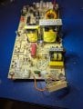
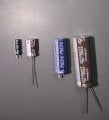
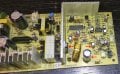
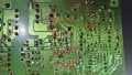
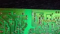
I am attaching 4 photos... PCB topside before fixing(arrows show the components to be replaced), Solderside showing burned Schottky before fixing, PCB solderside after fixing, and a picture comparing the capacitors and their replacements.

I would also like to express my disdain for the manufacturer of this board for using components that are not properly spec'd for their given tasks. These folks know how to design/build these things. They know they are using improper parts. Planned obsolesence or something else?
 

Attachments

Reporting success fixing the HYS80-12J. FX-101 FX102 schematics in the forum helped me to broadly understand the board.
* replaced all the el caps
* both primary side transistors 13005 were bust
* 2ohm and diode in related to one of 13005 - gone
* one of the secondary side driver transistors - gone

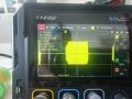
First I pulled all the bad components out together with secondary side transistors. Measured the rest of the diodes. I was worried that the opamp or TL494 would be impacted as well. Connected 10kOhm as a temporary replacement for NCT sensor and checked TL494 inputs and outputs. Then powered on the bench by providing 12V across C8. Found out that only half of the LM358 is used for NCT with other half unused. TL494 was providing a good output - apart from weird 50% @ 200Hz modulation of 29kHz wave, which was caused by the power sensing circuit floating. Once I pinned it I got a good B-E signal on 13005s. Then I put the new power transistors in and measured one more time on the bench with injected 12V on secondary side. Since the signal was even and in sync, I put it back together and it works as expected.

The board is fixable.
 

Attachments

Bob B.

Joined Oct 3, 2026
1
And still another success story! My Haier 12-bottle wine cooler, model HVT12ABS from 2005 quit cooling. I suspect it got damaged by a power surge during some recent violent thunderstorms. I replaced the Peltier unit, but then the fans would just quiver and not run. Many thanks to all who shared their experience and knowledge and guided me to replacing the C8 and C10 caps (both bad) on my control board! SUCCESS!!! - It runs and cools as it should again.

THANK YOU!!!
 

jbkeane

Joined Oct 19, 2026
1
Reporting another success story.

Model: Koolatron WC24MG, 24-bottle dual-zone "wine cellar", manufactured 02/21
PCB: FX-101 PCB121110K1 110

Symptoms: upper zone working fine; lower zone not working at all: fan not spinning, no cooling, LEDs on the PCB not illuminated
Solution: replaced C8

The longer story... I started by replacing both heatsink fans: the upper zone one was rattling badly, and the lower zone one rattled as well when tested on the bench. With the new fans in place I did some basic initial testing, verifying that the on-board fuse was OK, and that the board was receiving mains power. I tested the voltage across the peltier and found just 1.5VDC, compared with 10.6VDC for the working zone. Next I googled the number from the PCB and found the excellent summary article of this epic thread. I replaced C8 as advised with a 50V version and the lower zone was working! I tested the faulty C8 with a multifunction component tester: 44.4uF, 81-ohm ESR, 13% Vloss. I decided to replace C8 on the functional upper zone board as well, mostly because I wanted to see how bad it might be while still allowing normal operation: it tested as 47.4uF, 17-ohm ESR, 8.7% Vloss.

Many thanks to all the contributors to this site, and to this thread!
 
Thread starter Similar threads Forum Replies Date
SgtWookie Off-Topic 4
Top