Facebook
 Google
 GitHub
 Linkedin
Hello again,I really am paying attention but what is the #1 concern abut the parallels? There has been a lot of information and I am a bit mired down. Ill reread the posts in the meantime -
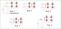
My component use in the 2 strings is the same type. Each string will be attached individually to the same Voltage source. I believe I have my power ratings calculated correctly. I have reduced he voltage source to 5V from 15V - although it wasn't clear that this needed to be done absolutely but I feel better about it.
What else do I need to address all of the parallel concerns.
In reference to paralleling two or more LED's.
If one LED has a characteristic voltage of say 3.1v and the other 3.2v, then the 3.2v LED will draw less current than the 3.1v LED when they are placed in parallel because the 3.1v LED will limit the voltage getting to the 3.2v LED and so the 3.1v LED gets hotter. How much hotter depends on what current you decide to run the pair at.
For example, since the pair together in the ideal case can draw twice the rated current of one, if you decide to run at 2 times the LED current (each LED just gets 1/2 of the total current) then one of them may be drawing more current than the other due to the difference in the LEDs. On the other hand, if you decide to drive them at the rated current of just ONE of the LEDs, then there is no problem because neither LED can get more than the rated current for one LED. There may be an issue of brightness however, where one appears brighter than the other.
In theory this isnt a concern unless of course you are using theory to design an actual circuit and then the theory would include the differences in LED's.
The main idea is that LED's are not like resistors they have differences that make a bigger electrical difference in a circuit then just the tolerance of some resistor would have.
I hope i have explained this better now but if not do not hesitate to ask about what is not clear.