Strain Gauges - Full Bridge Combinator and Amplification

Thread Starter

leogeo88

Joined Mar 13, 2019
12
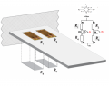
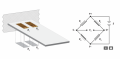
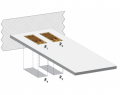
I am trying to build a thrust stand using a beam and strain gauges. I have attached the four strain gauges (350ohms) and have tested each individual one with the strain indicator box to verify that they work. My issue seems to be combining the four strain gauges into one value. I'm using the DAQ USB6009 to collect the data.
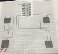
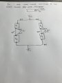
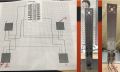
Attached you will find a picture of my schematic of the combinator and additional information regarding the strain gauges. I was getting rather weird values on Labview so I decided to use an oscilloscope to see the output.
The excitation voltage is 10V and I calculated that i should get about 2.41mv/V
When I place the oscilloscope I get values ranging from 2mv to 19mv and the values are bouncing in between. Do I at least have the correct schematic for connecting the strain gauges to the DAQ?
Any help is appreciated. Thank you in advance
 

Attachments

sghioto

Joined Dec 31, 2017
8,634
I don't understand the wiring on the strain gauges. Normally the gauges
are connected in a bridge circuit configuration as below. Use the differential input on the USB6009
SG

EEE strain gauge USB6009.PNG
 
Last edited:

ericgibbs

Joined Jan 29, 2010
21,413
hi l88,
The long wiring to the strain gauges is not screened, also I do not see any noise filtering on the bridge output connecting to the 6008.
I suspect your bouncing is due to electrical noise pick up, also are the metal plates to which the SG's are fixed connected to Common/0v.??
E

AA1 14-Mar-19 08.23.gif
 

Thread Starter

leogeo88

Joined Mar 13, 2019
12
I don't understand the wiring on the strain gauges. Normally the gauges
are connected in a bridge circuit configuration as below. Use the differential input on the USB6009
SG

View attachment 172273
I don't have much experience with this. I used three wires because that is what you are supposed to use when using the strain indicator box (P3500), so I assumed it was the same thing.
 

Thread Starter

leogeo88

Joined Mar 13, 2019
12
hi l88,
The long wiring to the strain gauges is not screened, also I do not see any noise filtering on the bridge output connecting to the 6008.
I suspect your bouncing is due to electrical noise pick up, also are the metal plates to which the SG's are fixed connected to Common/0v.??
E

View attachment 172284
No, the metal plates to which the strain gauges are applied are not connected to common ground. After ericgibbs mentioned it, now I'm wondering if my three wire setup is even correct and instead should go with two wires. http://www.vishaypg.com/docs/11092/tt612.pdf
I read that three wires are added for bridge balance
 

ericgibbs

Joined Jan 29, 2010
21,413
hi,
Post a circuit schematic showing how the SG's are interconnected , show excitation voltage and signal take off points.
E
 

ericgibbs

Joined Jan 29, 2010
21,413
hi,
I see that OK.
Post a drawing showing the R1,R2,R3,R4 SG's , how they are connected and which face of the metal sheet they fixed, ie: Compression or Tension.
E

EDIT:
This is the way I see it.
The White wires on each SG are connected to the same SG pad.
 

Attachments

Last edited:

Thread Starter

leogeo88

Joined Mar 13, 2019
12
hi,
There are 3 wires on each SG, but the two White wires are connected to the same point on the SG. ie: linked together.

E
Oh, I understand what you are saying. I agree with your schematic. I will try this out and see what I get. It looks right. Thank you very much for your help throughout this. Very much appreciated
 

sghioto

Joined Dec 31, 2017
8,634
The image posted in #14 is correct. You need to keep the wiring between the gauges as short as possible. For best results connect a 4 conductor shielded cable from the load cell to the 6009. Connect the shield conductor to the metal plate.
SG
 
Last edited:

Thread Starter

leogeo88

Joined Mar 13, 2019
12
Hi,

When I tried doing that wheatstone bridge configuration in #14 my output at the S+ and S- using an oscilloscope is 2.55V. Shouldn't my output from the wheatstone be in mV?

Thank you
 

sghioto

Joined Dec 31, 2017
8,634
Shouldn't my output from the wheatstone be in mV?
Correct! The voltage should be zero if all the strain gauges have equal resistance and there is no stress.
To test for continuity you should read 2.5 volts from zero volts to the white wires on both sides of the bridge.
SG
 
Last edited:

Thread Starter

leogeo88

Joined Mar 13, 2019
12
Correct! The voltage should be zero if all the strain gauges have equal resistance and there is no stress.
To test for continuity you should read 2.5 volts from zero volts to the white wires on both sides of the bridge.
SG
Thank you Sghioto for your quick reply. I uploaded an image of the wheatstone bridge with the formula. My belief was that the output (Vout), or in my case S+ and S-, would be in millivolts. Am I not understanding this correctly?
 

Attachments

Top