 Facebook
 Google
 GitHub
 Linkedin
Hello. I am struggling to understand how to properly use SPI interface.
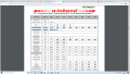
As far as I understand, every SPI communication starts with an instruction byte which specifies whether we want to READ or WRITE and then followed by a register address. After that, the DATA that we want to write or read.
SPI slave device:
https://www.mouser.co.uk/datasheet/2/949/w25m02gv_revf_050918_unsecured-1489896.pdf
Something like that :

I have generated my STM32 project using STM32cubeMX and the generated SPI libraries dont make any sense to me at all.
This is the generated code for the SPI transmit, however, I dont seem to understand how do I address the instruction byte and the register address?
Have anyone used stm32cubemx generated SPI library and could give me some guidance?
As far as I understand, every SPI communication starts with an instruction byte which specifies whether we want to READ or WRITE and then followed by a register address. After that, the DATA that we want to write or read.
SPI slave device:
https://www.mouser.co.uk/datasheet/2/949/w25m02gv_revf_050918_unsecured-1489896.pdf
Something like that :
I have generated my STM32 project using STM32cubeMX and the generated SPI libraries dont make any sense to me at all.
C:
HAL_StatusTypeDef HAL_SPI_Transmit(SPI_HandleTypeDef *hspi, uint8_t *pData, uint16_t Size, uint32_t Timeout)
{
  uint32_t tickstart;
  HAL_StatusTypeDef errorcode = HAL_OK;
  uint16_t initial_TxXferCount;

  /* Check Direction parameter */
  assert_param(IS_SPI_DIRECTION_2LINES_OR_1LINE(hspi->Init.Direction));

  /* Process Locked */
  __HAL_LOCK(hspi);

  /* Init tickstart for timeout management*/
  tickstart = HAL_GetTick();
  initial_TxXferCount = Size;

  if (hspi->State != HAL_SPI_STATE_READY)
  {
    errorcode = HAL_BUSY;
    goto error;
  }

  if ((pData == NULL) || (Size == 0U))
  {
    errorcode = HAL_ERROR;
    goto error;
  }

  /* Set the transaction information */
  hspi->State       = HAL_SPI_STATE_BUSY_TX;
  hspi->ErrorCode   = HAL_SPI_ERROR_NONE;
  hspi->pTxBuffPtr  = (uint8_t *)pData;
  hspi->TxXferSize  = Size;
  hspi->TxXferCount = Size;

  /*Init field not used in handle to zero */
  hspi->pRxBuffPtr  = (uint8_t *)NULL;
  hspi->RxXferSize  = 0U;
  hspi->RxXferCount = 0U;
  hspi->TxISR       = NULL;
  hspi->RxISR       = NULL;

  /* Configure communication direction : 1Line */
  if (hspi->Init.Direction == SPI_DIRECTION_1LINE)
  {
    SPI_1LINE_TX(hspi);
  }

#if (USE_SPI_CRC != 0U)
  /* Reset CRC Calculation */
  if (hspi->Init.CRCCalculation == SPI_CRCCALCULATION_ENABLE)
  {
    SPI_RESET_CRC(hspi);
  }
#endif /* USE_SPI_CRC */

  /* Check if the SPI is already enabled */
  if ((hspi->Instance->CR1 & SPI_CR1_SPE) != SPI_CR1_SPE)
  {
    /* Enable SPI peripheral */
    __HAL_SPI_ENABLE(hspi);
  }

  /* Transmit data in 16 Bit mode */
  if (hspi->Init.DataSize == SPI_DATASIZE_16BIT)
  {
    if ((hspi->Init.Mode == SPI_MODE_SLAVE) || (initial_TxXferCount == 0x01U))
    {
      hspi->Instance->DR = *((uint16_t *)hspi->pTxBuffPtr);
      hspi->pTxBuffPtr += sizeof(uint16_t);
      hspi->TxXferCount--;
    }
    /* Transmit data in 16 Bit mode */
    while (hspi->TxXferCount > 0U)
    {
      /* Wait until TXE flag is set to send data */
      if (__HAL_SPI_GET_FLAG(hspi, SPI_FLAG_TXE))
      {
        hspi->Instance->DR = *((uint16_t *)hspi->pTxBuffPtr);
        hspi->pTxBuffPtr += sizeof(uint16_t);
        hspi->TxXferCount--;
      }
      else
      {
        /* Timeout management */
        if ((((HAL_GetTick() - tickstart) >=  Timeout) && (Timeout != HAL_MAX_DELAY)) || (Timeout == 0U))
        {
          errorcode = HAL_TIMEOUT;
          goto error;
        }
      }
    }
  }
  /* Transmit data in 8 Bit mode */
  else
  {
    if ((hspi->Init.Mode == SPI_MODE_SLAVE) || (initial_TxXferCount == 0x01U))
    {
      *((__IO uint8_t *)&hspi->Instance->DR) = (*hspi->pTxBuffPtr);
      hspi->pTxBuffPtr += sizeof(uint8_t);
      hspi->TxXferCount--;
    }
    while (hspi->TxXferCount > 0U)
    {
      /* Wait until TXE flag is set to send data */
      if (__HAL_SPI_GET_FLAG(hspi, SPI_FLAG_TXE))
      {
        *((__IO uint8_t *)&hspi->Instance->DR) = (*hspi->pTxBuffPtr);
        hspi->pTxBuffPtr += sizeof(uint8_t);
        hspi->TxXferCount--;
      }
      else
      {
        /* Timeout management */
        if ((((HAL_GetTick() - tickstart) >=  Timeout) && (Timeout != HAL_MAX_DELAY)) || (Timeout == 0U))
        {
          errorcode = HAL_TIMEOUT;
          goto error;
        }
      }
    }
  }
This is the generated code for the SPI transmit, however, I dont seem to understand how do I address the instruction byte and the register address?
Have anyone used stm32cubemx generated SPI library and could give me some guidance?
Attachments
-
 142 KB Views: 6
 -
 212.4 KB Views: 6


