Stereo started smoking!!!!!!!

Thread Starter

EarlAnderson

Joined Nov 13, 2011
166
Not on emitter.

Across the 0.47R Emitter resistors.

First measure the voltage drop across the 0.47R emitter resistor The amp shud be in idle mode. Volume down & the amp should be left on for around 10m to warm up to do this.

Measure each and post ur results. Do not turn the VR's
When i connect my multimeter, i dont get any reading
 

Thread Starter

EarlAnderson

Joined Nov 13, 2011
166
1) Make sure it's set to voltage mode
2) If it's a manual multimeter, set it to the 9 volt setting, and keep lowering it until you get a reading
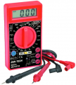
I had mine set down to lowest setting. Mine goes down to 200mV. I have one of those cheap $5 harbor-freight multimeters tho, im sure that doesnt help much
 

R!f@@

Joined Apr 2, 2009
10,014
Measure the base voltage at each out put transistor. Negative probe should be connected to ground.

Let the amp warm up before measurements.

The voltage range will be from 0.3VDC to 0.6VDC at the base of the out put devices.
Careful when u measure them. A slip of the probe and u will be crying.
 

Thread Starter

EarlAnderson

Joined Nov 13, 2011
166
Measure the base voltage at each out put transistor. Negative probe should be connected to ground.

Let the amp warm up before measurements.

The voltage range will be from 0.3VDC to 0.6VDC at the base of the out put devices.
Careful when u measure them. A slip of the probe and u will be crying.
Well this is weird. I have -30V on the first one, 0.73V on the second one, 0.36V on the third one, and -30V on the fourth one
 

R!f@@

Joined Apr 2, 2009
10,014
It's OK.

Where did u ground the meter. Try to use the speaker ground as the ground to measure the voltage

Shooot ! I 4 got

It's not a complementary stage. What u get is correct.

U have to connect the meter across Base and emitter.
 

R!f@@

Joined Apr 2, 2009
10,014
And if u cannot get the milliVoltmeter range then it is quite difficult to properly adjust the idle current. Which is same as the biasing or the 25mV voltage drop across the emitter resistor.

If everything is OK. U can remove the 22R resistors and solder the wires properly and do a test run on the amp.
 

Thread Starter

EarlAnderson

Joined Nov 13, 2011
166
It's OK.

Where did u ground the meter. Try to use the speaker ground as the ground to measure the voltage

Shooot ! I 4 got

It's not a complementary stage. What u get is correct.

U have to connect the meter across Base and emitter.
Okay i got 0.62 on the first 2 and 0.33 on the second 2
 

Thread Starter

EarlAnderson

Joined Nov 13, 2011
166
I am also noticing a slight bit of "hum" when i connect the speakers. Im guessing bad caps, which ill replace after everythings up and running
 
Last edited:

Thread Starter

EarlAnderson

Joined Nov 13, 2011
166
Just out of curiosity, I adjusted the pots on the amplifier board, to see if that would cancel out any hum. Not only did it cancel out the hum in the speakers, but now the 22R resistors arent even warm, and the heatsink is barely warm at all. I think the amplifier was obviously overbiased
 

R!f@@

Joined Apr 2, 2009
10,014
The readings tells u tht it is indeed out of bias, u see the readings across each transistor shud be approx 0.55V.

0.33V won't even bias the transistor into linear region. 0.62V will saturate the transistor too soon..

The best way is to measure the 25mV across the emitter resistor.
The +25mV across the positive side and the -25mV across the negative side will cancel out giving u 0VDC at the speaker terminal when the transistors are properly biased.
 

Thread Starter

EarlAnderson

Joined Nov 13, 2011
166
The readings tells u tht it is indeed out of bias, u see the readings across each transistor shud be approx 0.55V.

0.33V won't even bias the transistor into linear region. 0.62V will saturate the transistor too soon..

The best way is to measure the 25mV across the emitter resistor.
The +25mV across the positive side and the -25mV across the negative side will cancel out giving u 0VDC at the speaker terminal when the transistors are properly biased.
I dont get any reading when i connect the multimeter across the resistors. I know my multimeter measures millivolts.
 

wayneh

Joined Sep 9, 2010
18,183
I dont get any reading when i connect the multimeter across the resistors.
Do you mean your reading is 0.0mV, when the meter is set to its 200mV scale? You really should not have any problem measuring in the necessary range. These cheap meters may not be super accurate at 20mV, but you should certainly get a reading that's within 10% or better. When mine reads 10.0mV, I believe it.
 

Thread Starter

EarlAnderson

Joined Nov 13, 2011
166
Okay i adjusted the pots to so that theres around 0.55V on the base of each transistor, but theres still some DC voltage on the speaker terminals, and I also hear this weird popping noise in the speaker if i turn the volume up with music playing through it
 
Last edited:
Thread starter Similar threads Forum Replies Date
M Technical Repair 23
Top