Facebook
 Google
 GitHub
 Linkedin
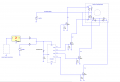
I am currently working on a project that uses a stepper motor and a PIC16F887 micro controller to run it. The motor is rated for 7V and I have a 7V supply to the motor and the driver circuit. The Micro controller is run off 5V. I wrote a simple program for troubleshooting that should just step the motor every 5 seconds. I also output the value to my LED's on my board so I can tell that the correct sequence is being outputted to the motor. The problem is, the LED's are showing the correct output but nothing is happening with the motor. I am reading the voltage across the output wire to the breadboard from the microcontroller and when high it is only 3.5V instead of the 5V it should be. Then at my last FET, the voltage across the output is only .4V when high. I have been trying to troubleshoot this for a while and I am stuck. I attached a picture of my driver circuit... and my assembly language program is below. Any help or suggestions would be greatly appreciated. The part I finished was for a school project, but this is more for personal use now and I don't have much experience in troubleshooting circuits like this yet. Thanks in advance.
It is my troubleshooting code so there is not much organization.
list p=16f887 ; list directive to define processor
#include <p16f887.inc> ; processor specific variable definitions
; '__CONFIG' directive is used to embed configuration data within .asm file.
; The labels following the directive are located in the respective .inc file.
; See respective data sheet for additional information on configuration word.
__CONFIG _CONFIG1, _LVP_OFF & _FCMEN_OFF & _IESO_OFF & _BOR_OFF & _CPD_OFF & _CP_OFF & _MCLRE_OFF & _PWRTE_ON & _WDT_OFF & _INTRC_OSC_NOCLKOUT
__CONFIG _CONFIG2, _WRT_OFF & _BOR21V
cblock 0x20
Direction ; Motor Direction (Left/Right)
Delay1ms ; 1ms Delay
Delay250ms ; 250ms Delay
Delay1s ; 1s delay
Delay30s ; 30s delay
Delay11
Delay22
d1
d2
d3
temp
endc
;Index1 equ b'1001' ; Stepper motor pos1
;Index2 equ b'1100' ; Stepper motor pos2
;Index3 equ b'0110' ; Stepper motor pos3
;Index4 equ b'0011' ; Stepper motor pos3
Index1 equ b'00001001'
Index2 equ b'00001010'
Index3 equ b'00000110'
Index4 equ b'00000101'
ORG 0 ; processor reset vector
goto Main ; go to beginning of program
Main:
bcf STATUS,RP1 ; Select register bank 0
bcf STATUS,RP0
clrf PORTC
clrf PORTD
bsf STATUS,RP0 ; Bank Select 1
clrf TRISC ; Set PORTC as outputs (For motor)
clrf TRISD
bcf STATUS,RP0 ; Back to bank 0
bcf STATUS,RP1
movlw Index1
movwf PORTC
movwf PORTD
call Delay5
movlw Index2
movwf PORTC
movwf PORTD
call Delay5
movlw Index3
movwf PORTC
movwf PORTD
call Delay5
movlw Index4
movwf PORTC
movwf PORTD
call Delay5
goto Main
OndelayLoop:
decfsz Delay11,f ; Waste time.
goto OndelayLoop ; The Inner loop takes 3 instructions per loop * 256 loopss = 768 instructions
decfsz Delay22,f ; The outer loop takes and additional 3 instructions per lap * 256 loops
goto OndelayLoop ; (768+3) * 256 = 197376 instructions / 1M instructions per second = 0.197 sec.
; call it two-tenths of a second.
return
Delay5:
;4999993 cycles
movlw 0x2C
movwf d1
movlw 0xE7
movwf d2
movlw 0x0B
movwf d3
Delay_0:
decfsz d1, f
goto $+2
decfsz d2, f
goto $+2
decfsz d3, f
goto Delay_0
;3 cycles
goto $+1
nop
;4 cycles (including call)
return
It is my troubleshooting code so there is not much organization.
list p=16f887 ; list directive to define processor
#include <p16f887.inc> ; processor specific variable definitions
; '__CONFIG' directive is used to embed configuration data within .asm file.
; The labels following the directive are located in the respective .inc file.
; See respective data sheet for additional information on configuration word.
__CONFIG _CONFIG1, _LVP_OFF & _FCMEN_OFF & _IESO_OFF & _BOR_OFF & _CPD_OFF & _CP_OFF & _MCLRE_OFF & _PWRTE_ON & _WDT_OFF & _INTRC_OSC_NOCLKOUT
__CONFIG _CONFIG2, _WRT_OFF & _BOR21V
cblock 0x20
Direction ; Motor Direction (Left/Right)
Delay1ms ; 1ms Delay
Delay250ms ; 250ms Delay
Delay1s ; 1s delay
Delay30s ; 30s delay
Delay11
Delay22
d1
d2
d3
temp
endc
;Index1 equ b'1001' ; Stepper motor pos1
;Index2 equ b'1100' ; Stepper motor pos2
;Index3 equ b'0110' ; Stepper motor pos3
;Index4 equ b'0011' ; Stepper motor pos3
Index1 equ b'00001001'
Index2 equ b'00001010'
Index3 equ b'00000110'
Index4 equ b'00000101'
ORG 0 ; processor reset vector
goto Main ; go to beginning of program
Main:
bcf STATUS,RP1 ; Select register bank 0
bcf STATUS,RP0
clrf PORTC
clrf PORTD
bsf STATUS,RP0 ; Bank Select 1
clrf TRISC ; Set PORTC as outputs (For motor)
clrf TRISD
bcf STATUS,RP0 ; Back to bank 0
bcf STATUS,RP1
movlw Index1
movwf PORTC
movwf PORTD
call Delay5
movlw Index2
movwf PORTC
movwf PORTD
call Delay5
movlw Index3
movwf PORTC
movwf PORTD
call Delay5
movlw Index4
movwf PORTC
movwf PORTD
call Delay5
goto Main
OndelayLoop:
decfsz Delay11,f ; Waste time.
goto OndelayLoop ; The Inner loop takes 3 instructions per loop * 256 loopss = 768 instructions
decfsz Delay22,f ; The outer loop takes and additional 3 instructions per lap * 256 loops
goto OndelayLoop ; (768+3) * 256 = 197376 instructions / 1M instructions per second = 0.197 sec.
; call it two-tenths of a second.
return
Delay5:
;4999993 cycles
movlw 0x2C
movwf d1
movlw 0xE7
movwf d2
movlw 0x0B
movwf d3
Delay_0:
decfsz d1, f
goto $+2
decfsz d2, f
goto $+2
decfsz d3, f
goto Delay_0
;3 cycles
goto $+1
nop
;4 cycles (including call)
return
Attachments
-
 23.5 KB Views: 39