
 Facebook
 Google
 GitHub
 Linkedin
Greetings - I'm new & just found this great site.
Sorry, I can't get my pics to show larger.
Questions for motor brainiacs...
Motor appears to be wired permanently for 110VAC; Run windings are joined internally {with T1 to T3 and T2 to T4}
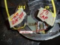
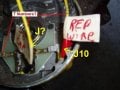
Motor has a three-wire "stationary" switch controlled by the centrifugal/mechanical switch. One internal wire [marked "J something"] goes to one terminal of Cap; the other two wires [J10 & J11] go to external wires [a Red and a White/Black, respectively].
The "Other" Cap wire [internally marked T8] goes to Start winding. The Start winding then goes externally to T5, a White wire.
This trolley motor direction was constantly reversed.
Questions:
How does this stationary switch work? How is it hooked up externally to provide for CW/CCW rotation?
If say, the T5 wire was wired HOT/L1, what did they do with J10 & J11? I am assuming this scheme is for CW/CCW control....???
The external Blue & Orange wires go to an internal "Thermostat" buried within the stator...are these the typical P1 & P2? If so, is the thermostat wired externally to some over-temp alarm, or is it wired in series with the Run windings?
Thanks!
Sorry, I can't get my pics to show larger.
Questions for motor brainiacs...
Motor appears to be wired permanently for 110VAC; Run windings are joined internally {with T1 to T3 and T2 to T4}
Motor has a three-wire "stationary" switch controlled by the centrifugal/mechanical switch. One internal wire [marked "J something"] goes to one terminal of Cap; the other two wires [J10 & J11] go to external wires [a Red and a White/Black, respectively].
The "Other" Cap wire [internally marked T8] goes to Start winding. The Start winding then goes externally to T5, a White wire.
This trolley motor direction was constantly reversed.
Questions:
How does this stationary switch work? How is it hooked up externally to provide for CW/CCW rotation?
If say, the T5 wire was wired HOT/L1, what did they do with J10 & J11? I am assuming this scheme is for CW/CCW control....???
The external Blue & Orange wires go to an internal "Thermostat" buried within the stator...are these the typical P1 & P2? If so, is the thermostat wired externally to some over-temp alarm, or is it wired in series with the Run windings?
Thanks!
Attachments
-
 72.2 KB Views: 23
 -
 64.9 KB Views: 22






