We will NOT just do YOUR homework. You need to show YOUR best attempt to work the problem as far as you can. We can then look at your work and point out where you are going wrong and make suggestions to help you get a bit further, but YOU must do the bulk of the work, otherwise you will get virtually nothing out of it.
Have you done any of these problems before this?
Do you know how to model the inductor L and capacitor C in a form suitable for use in state space?
You can start with the differential form of the definitions for both L and C.
One way of looking at it is that L and C are both current sources and voltage sources but the expressions involve a time derivative for each.
See if you can make sense of this by using the differential forms and go from there.
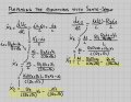
1) I started by defining the inputs, the outputs and the states.
2) Then I isolated the dynamic equations with the derivatives (in this case voltage on inductor and current on capacitor).
3) Finally, I replaced the two equations containing the derivatives with those of the States-Space.
I enclose photos of the steps and ask for feedback so that I can continue and derive the matrices A, B, C and D.
I also ask for confirmation whether the red writing is correct.
We will NOT just do YOUR homework. You need to show YOUR best attempt to work the problem as far as you can. We can then look at your work and point out where you are going wrong and make suggestions to help you get a bit further, but YOU must do the bulk of the work, otherwise you will get virtually nothing out of it.
1) I started by defining the inputs, the outputs and the states.
2) Then I isolated the dynamic equations with the derivatives (in this case voltage on inductor and current on capacitor).
3) Finally, I replaced the two equations containing the derivatives with those of the States-Space.
I enclose photos of the steps and ask for feedback so that I can continue and derive the matrices A, B, C and D.
I also ask for confirmation whether the red writing is correct.
If you have trouble understanding this notation refer to the image attached.
I use the notation of upper case for the state variable and lower case for the derivative, so:
X1 is the current through L
X2 is the voltage across C
x1 is the derivative of the current through L
x2 is the derivative of the voltage across C
So X1 and X2 are the state vars and if we were to use dots then
dot_X1 is x1
dot_X2 is x2
I think that should be easy enough to understand. This makes typing the expressions out easier and clear.
We could also use x1 and .x1 and x2 and .x2 but that doesnt seem as clear.
If you have a problem reading this though i'll make an image instead.
Ok so you are defining:
x1=L*di/dt
x2=C*dv/dt
is that right?
If so, that is correct. That however does not solve for the set of state space equations are you aware of that?
If not in standard matrix form, then i would expect to see this form for the equations:
L*x1=fa(R1,R2,...,etc)
C*x2=fb(R1,R2,...,etc)
where fa and fb are functions of the component values and the source voltages, and the storage elements L and C appear on the left multiplied by the derivatives of the state variables.
Ultimately then you can divide the first equation by L and the second equation by C to obtain:
x1=fa(...)/L
x2=fb(...)/C
and then you have the two equations required to solve the network with a possible 3rd to show the output:
In the notation with the dots (the input voltage source is E):
x1=fa(E,X1,X2,R1,R2,L,C)
x2=fb(E,X1,X2,R1,R2,L,C)
Vout=fc(E,X1,X2,R1,R2,L,C)
and there i am showing all the possible variables in both functions although some of those may not be needed in both equations.
1) If x1 is the derivative of the current through L .. then it should be di/dt .. not L*di/dt
I mean .. when you write: Ok so you are defining:
x1=L*di/dt
are you referring to my example or is that what you would do?
2) It is not very clear to me how to proceed after you have found the functions fa and fb.
I found this method online for writing the state space model, I find it quite good and would like to follow it, although I don't know if it can be applied to this exercise.
Yes sorry i meant that x1=di/dt and of course x2=dv/dt for the cap.
The left side of the equations would still be x1*L and x2*C until you divide by L and C for each.
The functions fa and fb are just representative of what you will end up with. Two functions one with the derivative x1 and one with x2. You basically solve for the two derivatives then you can use standard methods to get the frequency expressions and the time expressions.
The simplest method is to solve for the central node voltage in terms of only X1 an X2 (the state variables) and possibly the input source voltage, and then you can use that to form the solutions for x1 and x2. It's actually a lot simpler than it looks you can even use Nodal Analysis to find the voltage of that central node.
I can show you how to do this and i think you may be surprised at how easy it can be, but i will look at the method you linked too also and see what i think, and i'll get back here.
I attached the new calculations I have done and I think I have managed to arrive at the correct result, maybe there is some miscalculation and a few wrong marks but the rest seems correct to me.
I attached the new calculations I have done and I think I have managed to arrive at the correct result, maybe there is some miscalculation and a few wrong marks but the rest seems correct to me.
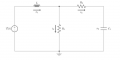
They look correct (second image) but it's a little hard to follow reading someone else's handwriting. You can check with my solutions.
Vx is the central node voltage and you can see how the solution for x1*L comes out so simply.
E is the input source voltage.
I looked at your link briefly and that is not a general state space method it looks more like a differential equation to state space form method which i dont think you need here.
It's good to know that too.
It's harder to go the other way though, from a set of ODE's (or state space) to a regular differential equation.
 Facebook
 Google
 GitHub
 Linkedin

 19.9 KB Views: 0