 Facebook
 Google
 GitHub
 Linkedin
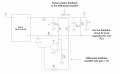
Following is the circuit I have been analyzing:

This is a buck regulator. Circuit description:
Input voltage : 12 V
Output voltage : 3.3 V
Feedback-path -> Combination of R1 and R2
Additional path -> Differential amplifier path that will be triggered once voltage across the sense resistor voltage is enough to turn-on the diode
Feedback voltage = 1 V
I am interested to calculate phase-margin and gain-margin. If any of you have much idea about transfer-function and feedback stability analysis, kindly advice.Please let me know if their is any further information required.
Attachments
-
 267.6 KB Views: 30


