Hi Dana - thanks for replying. Here goes - I am using a pic16f628 with sck driven by one of the standard cmos outputs, but sda driven by an open drain with 10k pullup. There is no need for the sck line to be used by any other master
I am using the power-on reset with the the lcd reset input wired to +5v.
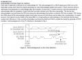
In software I wait for about 50ms after switch on, then execute code which produces the clock (yellow) and data (blue) signals shown on the attached scope screenshot. This sequence is Start, slave address with write (01111100), followed by 'getack'.
The getack routine switches the pic sda port to input (porta,4 open drain with 10k pullup), reads the sda bit (porta,4) and loops till it goes low.
You can see from the scope trace that the data does not go low during the ack clock high state. The state shown on the left of the screen (sck high, sda high) continues indefinitely, and the prog hangs up at this point.
This is the getack routine -
;------------------------------------------------
getack ;read acknowledge signal from serial device, wait for it to go low before exit.
agn call edel ;delay
bsf status,rp0 ;Switch to register bank 1
bsf trisa,4 ;set sda bit to input
bcf status,rp0 ;Switch Back to reg. Bank 0
bsf portb,1 ;write scl hi
call edel ;delay
acklp btfsc porta,4 ;read sda bit in porta
goto acklp ;loop if ack signal is high
;ack is now low
bcf portb,1 ;write sck low
call edel;delay
bcf porta,4 ;set sda low pending trisa
bsf status,rp0 ;Switch to register bank 1
bcf trisa,4 ;set sda bit to output
bcf status,rp0 ;Switch Back to reg. Bank 0
return
;------------------------------------------------
I am beginning to wonder whether the module has been damaged. I have used the common parallel-data modules a lot, and when they are powered up without having been programmed they show a characteristic pattern on the screen - you can see the pixels, and some of the characters places on the first line appear blocked-out. But my serial module does not show this - it remains uniformly illuminated (grey) all over. Any ideas ?
QUOTE="danadak, post: 1284921, member: 527202"]What UP and IDE are you using ?
Using I2C as interface ? Typical problems not using the right slave
address, pullups on I2C line not correct or connected.
CLOCK SYNCHRONIZATION AND HANDSHAKING
Slave devices that need some time to process received byte or are not ready yet to send the next byte, can pull the clock low to signal to the master that it should wait. Once the clock is released the master can proceed with the next byte.
Ps - the waveform I have posted is a realisation of the first 10 bits shown in this pic taken from the datasheet for the device. It looks pretty perfect to me. But I have obviously missed something
Thanks for pointing this out - it might be significant, and I am so desperate I might try adding a bipolar transistor with a resistive collector load to create a wired AND for the SCK line. But at present I cannot see that this particular device supports the protocol you mention; there is nothing in the ST7032 data sheet which describes this usage. Attached is what the sheet says about ACK . I suppose I would have to add some code to getack to look at SCK as well as SDA and exit when both are low ? It seems hardly justified really , but if you can explain your line of thinking further I will deffo go for it.
I must say that the data sheet is full of inconsistencies and contradictions, for example the passage I have included mentions reading data from the LCD, but in another place says you can only write to it. Also the title of the passage I have attached is a most wonderful piece of ambiguity - it can be read two ways with opposite meanings according to whether 'not' is read as NOT (logical operator - "ACKlow is NOTBUSY"), or as vernacular 'not' - i.e. 'ACK does not function as a BUSY flag'. (I think it does in fact).
While writing this, it has occurred to me that ACK-low in i2c systems does not usually signify 'NOT BUSY' - rather it merely signifies acceptance of a byte. So the addition of a BUSY signal implies the need for something else - namely the use of SCK as you have mentioned. I propose to re-write GETACK so that it reads sck instead of instead of sda (with a bipolar wired-AND). What do you reckon ?
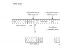
Read Busy Flag and AddressRead busy flag and address reads the busy flag (BF) indicating that the system is now internally operating
on a previously received instruction. If BF is 1, the internal operation is in progress. The next instruction
will not be accepted until BF is reset to 0. Check the BF status before the next write operation. At the same
time, the value of the address counter in binary AAAAAAA is read out. This address counter is used by
both CG and DDRAM addresses, and its value is determined by the previous instruction. The address
contents are the same as for instructions set CGRAM address and set DDRAM address.
Read Data from CG or DDRAMRead data from CG or DDRAM reads 8-bit binary data DDDDDDDD from CG or DDRAM.
The previous designation determines whether CG or DDRAM is to be read. Before entering this read
instruction, either CGRAM or DDRAM address set instruction must be executed. If not executed, the first
read data will be invalid. When serially executing read instructions, the next address data is normally read
from the second read. The address set instructions need not be executed just before this read instruction
when shifting the cursor by the cursor shift instruction (when reading out DDRAM). The operation of the
cursor shift instruction is the same as the set DDRAM address instruction.
Yes - you are right. I have used the parallel lcds based on the HD 44780 a lot, since the mid 1980s in fact, and this device ST032 is clearly based on the old chip - all of the commands, memory layout, etc are identical. It seems like a 44780 with an i2c interface bolted on. But my present interpretation of the data sheet is that you cannot read from the serial device as implemented in this case. Coming to this from the parallel lcd, I pondered exactly the point you are making, and worried over the meaning of 'Ack is not busy flag in i2c interface', thinking that this phrase is a warning that the busy flag must be read by extracting the HD 44780 status register and checking the 'busy' bit in the old way. But the data sheet as a whole makes much more sense if you understand the phrase to mean that you cannot read via the i2c interface and that ACK-low functions as NOTBUSY. Here, for example is part of a sample program which came with the device; the documentation suggests no other way for checking the busy flag -
/*******************************************************************************
*
Function Name : Check_Ack
* Description : Check acknowledge.
* Input : n
* Output : None
* Return : None
/
void Check_Ack(void)//Ó¦´ðλ
/*******************************************************************************
I do not recognise this programming language, but it seems clear that the function waits in a loop until ACK goes low - just as I have written my own getack routine. I have appended the complete data sheet in case you fancy studying it. Also the demo code
I am not I2C expert, I have to constantly go to website to read about the protocol.
Its a pain.
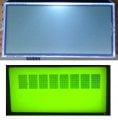
Hey Dana - thank you for discussing this with me. My latest thinking is that the module is damaged, so I have ordered a replacement. I feel that this evidence (attached pic) is relevant. The top pic is what my serial module looks like, while the bottom pic is what I have become accustomed to seeing when an HD 44780 parallel module is powered-up, but not programmed (i.e. the default power-up condition). The top pic does not look right at all, and given the similarities we have been discussing, I feel it must mean something.
Hey Dana - thank you for discussing this with me. My latest thinking is that the module is damaged, so I have ordered a replacement. I feel that this evidence (attached pic) is relevant. The top pic is what my serial module looks like, while the bottom pic is what I have become accustomed to seeing when an HD 44780 parallel module is powered-up, but not programmed (i.e. the default power-up condition). The top pic does not look right at all, and given the similarities we have been discussing, I feel it must mean something.
Don't know if your LCD is bricked or not, but the comparison pic is not a good indication in my opinion. Your top LCD is a COG (chip on glass) and is not going to look like the older LCD, especially before proper initialization.
No ACK is usually because the address is wrong as has already been posted and it doesn't look like you have the wrong address. Have you tried to slow the transmission speed way down (and with pull ups)? I know from working with similar (like a a 7036i, Newhaven NHD-C0220BiZ-FSW-FBW-3V3M), that they can be very slow and worked at 100 kbit/s but not 400 kbit/s [at 3.3V])?
You are using power on reset, have you tried resetting by attaching rst to a port and bringing it low with a healthy delay - see the code initialization section. That would be my best guess - that it is not resetting.
I have a couple of these hanging around and they also use a ST7032i (although I see you have a 2X8 and these are 2X16) - maybe it is time to see if they work .
Edited to add: if you don't have the caps and the VLCD line connected to 5V (assuming you are using it as a 5V display, I would expect what you are getting).
 Facebook
 Google
 GitHub
 Linkedin

") .
.


