Facebook
 Google
 GitHub
 Linkedin
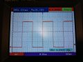
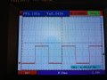
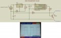
The height of the waveform should not drop! Unless you connect this 5k simulating resistor across the collector and emitter while still have R3 intact. You should place the simulating resistor in series with R3. We still dont know how much current this biological tissue can handle or need so you cant really calculate the value of R3
Square Wave with Variable Voltage
- Thread starter dan07
- Start date